Laser focusing optical system

A technology of optical system and laser light source, which is applied in the field of optical system to change the focusing position, can solve the problems of difficult and high-precision movement, and achieve the effects of easy automation, cost reduction and structural realization

Inactive Publication Date: 2007-03-07
OLYMPUS CORP
View PDF5 Cites 37 Cited by
  • Summary
  • Abstract
  • Description
  • Claims
  • Application Information

AI Technical Summary

Problems solved by technology

[0020] However, among the specimens placed on the stage, there are large specimens such as 12-inch wafers, and in order to move the position with

Method used


Image

  • Laser focusing optical system
  • Laser focusing optical system
  • Laser focusing optical system

Examples


Embodiment Construction

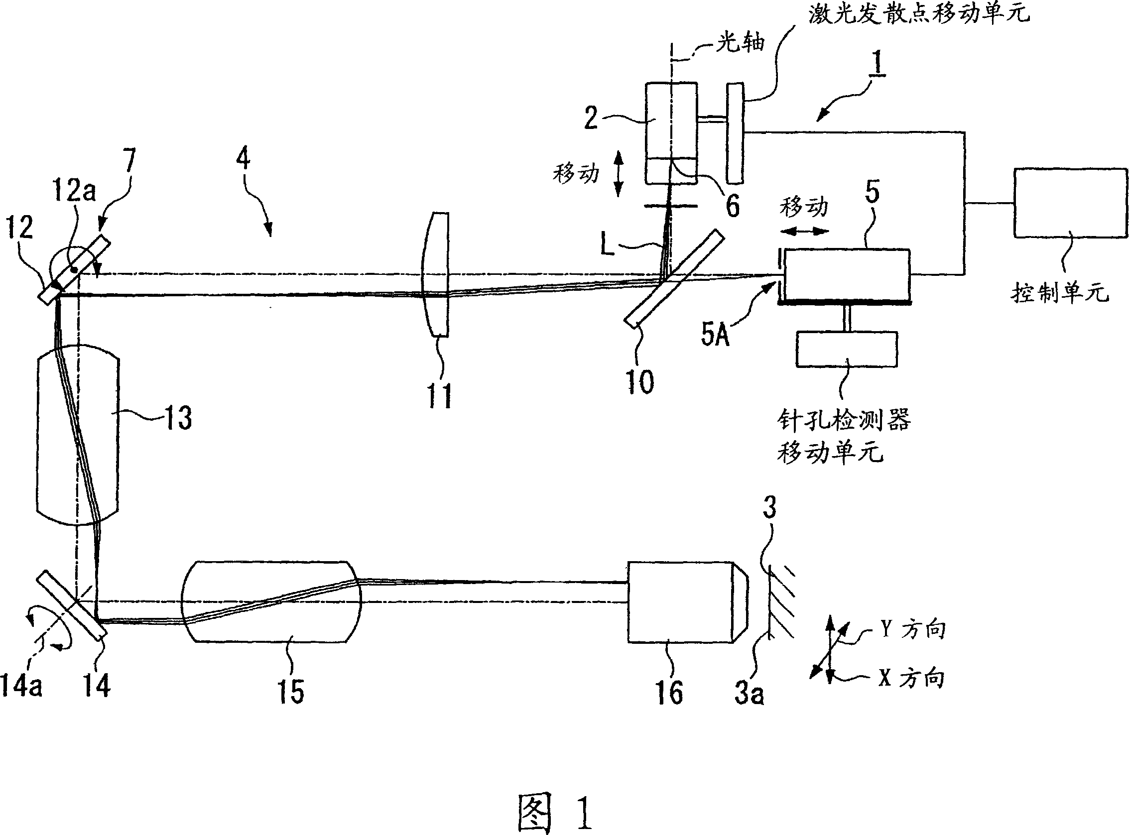
[0153] Hereinafter, a laser focusing optical system according to a first embodiment of the present invention will be described with reference to FIGS. 1 to 3 .

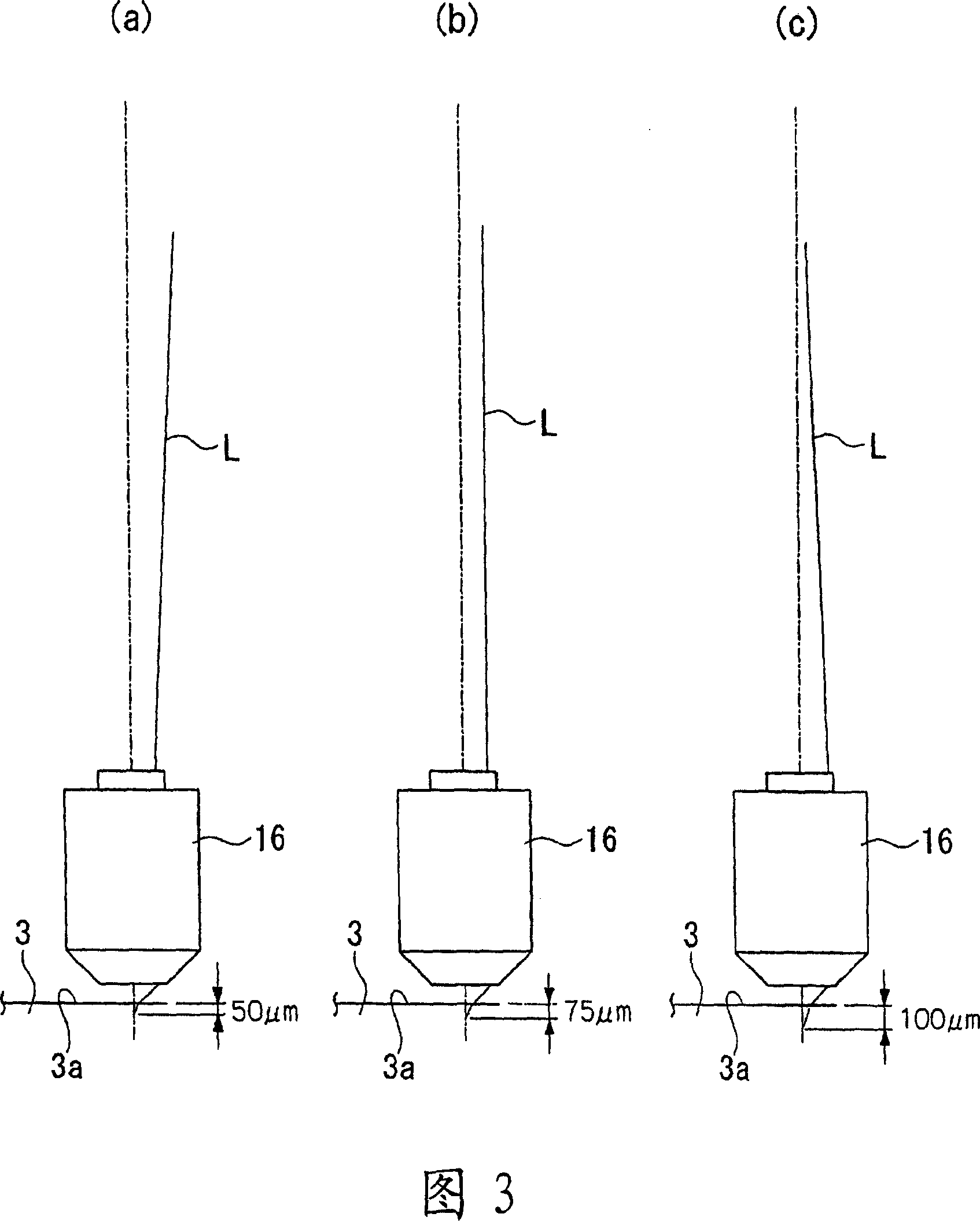
[0154] As shown in FIG. 1 , the laser condensing optical system 1 of the present embodiment has: a laser light source 2 that emits laser light L in a divergent light state (non-parallel beam state); Between the specimen (medium) 3, the laser light L is condensed in the specimen, and the light from the condensed point is refocused; the photodetector 5 (pinhole detector) is configured in a conjugated state with the laser light source 2 The position, through the pinhole 5A detects the light re-condensed by the condensing optical system 4; the laser divergence point moving unit, which corresponds to the refractive index of the sample 3 that makes the laser light L condensed and from the sample surface (surface of the sample) The distance from 3a to the light-gathering position can make the position of the laser divergence...


PUM


Abstract

A laser focusing optical system is provided with a laser beam source for projecting laser beams; a focusing optical system, which is arranged between the laser beam source and a medium to focus the laser beams in the medium and refocus the beams from the focusing point; a photodetector for detecting the beams refocused by the focusing optical system; and a laser emitting point shifting means, which can shift a position of the laser emitting point of the laser beams and a position of the photodetector, along an optical axis of the laser beams, corresponding to the refraction factor of the medium wherein the laser beams are focused and a distance between the surface of the medium and a focusing point.

Description

technical field [0001] The invention relates to a laser condensing optical system for condensing laser light to different parts in a medium. [0002] Furthermore, the present invention relates to an optical system capable of changing the position of a light source while keeping the amount of light incident on the pupil plane of the optical system and the distribution of the light amount constant. In particular, it relates to an optimal optical system capable of focusing light on parts having different depths in a medium, or an optical system suitable for changing the light focusing position. [0003] This application takes Japanese Patent Application No. 2004-132996 and Japanese Patent Application No. 2004-132994 as basic applications, and takes the contents thereof. Background technique [0004] Conventionally, there has been a demand to condense light at different depths in the medium, but in this case, spherical aberration occurs. For example, in the biological field, w...

Claims


Application Information

Patent Timeline
IPC IPC(8): G02B13/00G02B21/00G02B21/32
Inventor 江田幸夫安达贞志
Owner OLYMPUS CORP
Why Eureka
Try Eureka