Secondary roller mechanism for full computer flat knitting machine

A technology for flat knitting machines and auxiliary rollers, which is applied in knitting, weft knitting, textiles and papermaking, etc. It can solve the problems of high manufacturing cost, frequent adjustments, and easy slipping, etc., and achieves cost-saving manufacturing, simple overall structure, and easy to use. The effect of life extension

Inactive Publication Date: 2007-03-14
江苏雪亮电器机械有限公司
View PDF0 Cites 29 Cited by
  • Summary
  • Abstract
  • Description
  • Claims
  • Application Information

AI Technical Summary

Problems solved by technology

However, because a pair of rollers adopts a smooth surface roller structure, the following two shortcomings are exposed: one is that it is difficult to achieve sufficient parallelism in the installation or manufacture of a pair of rollers, so that there will be a gap between them Inconsistency, so that the pulling force can not be uniform, affecting the coiling effect of the coiling mechanism; second, because the length of a pair of rollers must be equal to the length of the needle plate of the flat knitting machine, so the lengthy rollers inevitably have deflection, and The existence of deflection will also cause uneven drawing force. If the pair of rollers are made thick in order to avoid or reduce the deflection, the distance between the rollers and the coils of the weaving mechanism will be too large, which will affect the weaving effect and quality.
Of course, it may be considered a beneficial move to reasonably set up supports between the intervals of the rollers to avoid deflection, but too many supports will affect the simplicity of the whole machine, and it is also difficult to control the unreasonable increase in cost The third is that in order to ensure the parallelism of a pair of rollers, adjustments must be made from time to time, resulting in frequent and labor-intensive adjustments
[0004] In view of the above deficiencies, the industry avoids using a pair of plum blossom rollers as the guide rollers. However, the following problems are caused: first, the plum blossom rollers are easy to deform, and the two ends are tight and the middle is loose, which makes it impossible to guide the fabric as a whole; The structure of the plum blossom roller will cause wrinkles on the surface of the fabric, making the fabric lose its original flatness; third, it needs two motors to cooperate with each other to move, so not only the assembly is difficult, but also the structure is complicated due to the large number of parts
However, this structure still exposes the following defects in actual use: first, since the first and second holster transition bars 6, 7 do not rotate, and the first and second holsters 10, 11 are in the first 1. Driven by the second bellows 8 and 9, it moves repeatedly, so whenever the first and second holsters 10 and 11 move a circle, they will rub against the first and second holster transition rods 6 and 7 Once, it doesn’t take long (generally 8 hours for a single shift is counted as 2 months), the first and second holsters 10 and 11 will be scrapped and must be replaced, and the time for replacing the holsters is very lengthy. One end of the holster transition rod 6,7 is unloaded from the first left and right bellows seats 2,3, or unloaded from the second left and right bellows seats 12,13, and then removed (pull out) the first , the second transition rod support 4,5, then put on the new first and second leather sheaths 10,11, then insert the first and second transition rod support 4,5, and finally insert the first and second transition rod supports 4,5 The second holster transition rod 6, 7 is fixed, and the first and second bellows 8, 9 are set
This will not only lengthen the downtime of the fully computerized flat knitting machine, affect the processing efficiency of the flat knitting machine, but also increase the cost of spare parts and the workload of the fitter; the first and second bellows 8, 9 and the motor The connection of the power output shaft of 1 is unreliable, and it is prone to slipping, which leads to the failure of the rotation of the first and second bellows 8, 9, and cannot drive the normal operation of the first and second leather sheaths 10, 11; the complete set of devices requires A pair of motors 1, so not only the structure lacks simplicity, but also the manufacturing cost is large

Method used


Image

  • Secondary roller mechanism for full computer flat knitting machine
  • Secondary roller mechanism for full computer flat knitting machine
  • Secondary roller mechanism for full computer flat knitting machine

Examples


Embodiment Construction

[0020] Through the applicant's description of the embodiments, it will be more helpful to understand the present invention, and make the positive effects of the present invention more manifest, but the embodiments should not be regarded as limiting the solution of the present invention.

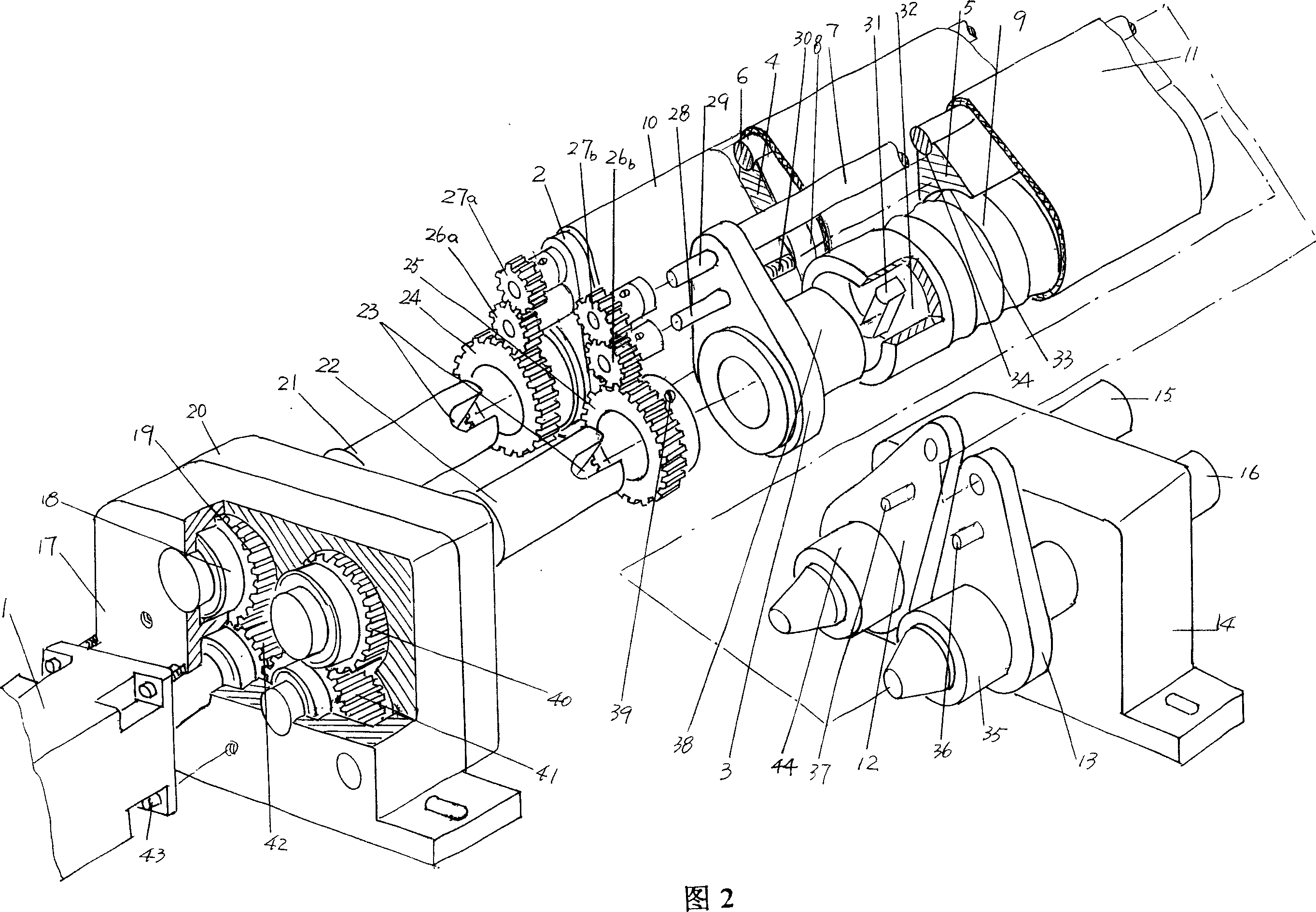
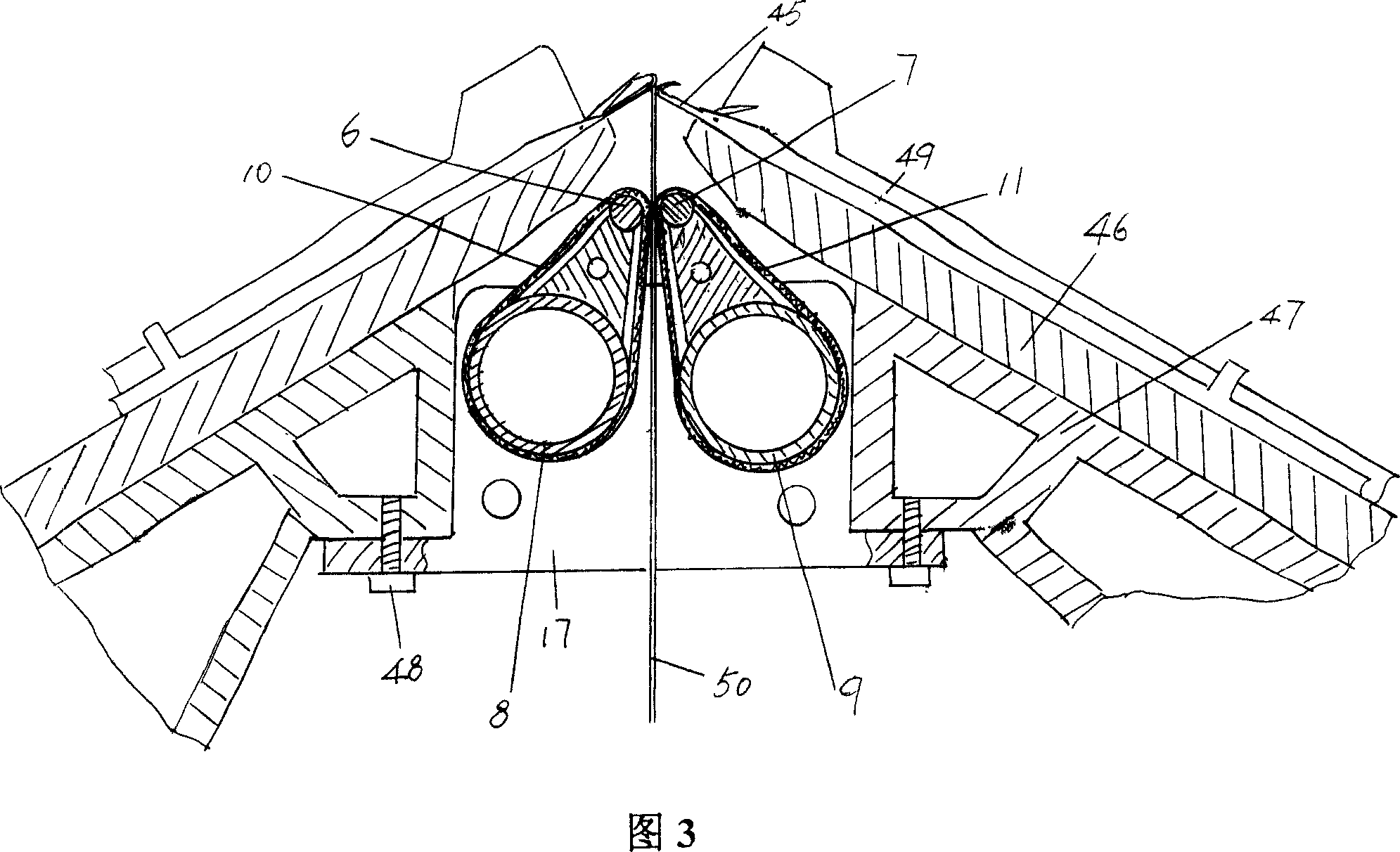
[0021]In Fig. 2, the gearbox 17 gear cover 20 as the power transmission device recommended by the present invention is fixed to the needle bed support 47 of the fully computerized flat knitting machine by fixing screws 48 (shown in Fig. 3) in the state of use. Yes, the motor 1 with forward and reverse functions is fixed with the gear box 17 by screws 43 . The power output shaft of the motor 1 extends into the cavity of the gear box 17 , and the driving gear 42 is fixed on the shaft end of the power output shaft of the motor 1 in the cavity of the gear box 17 . The first and second gear shafts 21 and 22 are respectively pivoted on the gear box 17 through bearings 18. Taking the position shown ...


PUM


Abstract

A auxiliary roller mechanism of all-computer flat knitting machine, comprising a power driving device, couple panel for a first left and right accordion pipe, couple panel for a second left and right accordion pipe, couple transition bar for a first and second leather cup, couple a first and second accordion pipe; couple strutting piece for a first and second transition bar, couple a first and second leather cup, characterized in that couple transition bar for a first and second leather cup is set rotationally on panels for a first and second left-and-right accordion pipes and on each ends there are a first and second transition bar gears connecting with power driving device, is belong to technology area for accessorial establishment of all-computer flat knitting machine. The merit of the mechanism is that there is no influence for efficiency of flat knitting machine because of replacing leather cup continually, working capacity of maintenance worker is lessen and only one electromotor is need for power driving mechanism so that there is less manufacturing cost.

Description

technical field [0001] The invention relates to a sub-roller mechanism of a fully computerized flat knitting machine, which is used to pull the fabric formed by the knitting mechanism downward under a clamping state for coiling by a coiling device, and belongs to the auxiliary facility technology of a fully computerized flat knitting machine field. Background technique [0002] On a flat knitting machine such as a fully computerized flat knitting machine, a supporting sub-roller mechanism is required. The so-called sub-roller mechanism is used for the weaving mechanism of the flat knitting machine in the weaving process. The lower traction is used for winding by the winding mechanism or cloth winding mechanism, because it is impossible for the winding mechanism to directly wind up the fabric, and if it is directly wound by the winding mechanism, the tension uniformity of the winding cloth cannot be obtained. , and it is impossible to wind up under the ideal moderate tension...

Claims


Application Information

Patent Timeline
Patent Type & Authority Applications(China)
IPC IPC(8): D04B15/90
Inventor 邵锡良
Owner 江苏雪亮电器机械有限公司
Why Eureka
Try Eureka