Inorganic cloth based folded lifting type fire-proof rolling shutter door
A fire shutter and lifting technology, applied in fire doors, door/window protection devices, shutters/movable grilles, etc., can solve the problems of inability to meet fire protection requirements and decoration effects, inability to roll, and large winding of the reel. , to achieve good decoration effect, meet fire protection requirements, save manpower
- Summary
- Abstract
- Description
- Claims
- Application Information
AI Technical Summary
Problems solved by technology
Method used
Image
Examples
Embodiment 1
[0014] Embodiment 1 As shown in Figures 1 and 2:
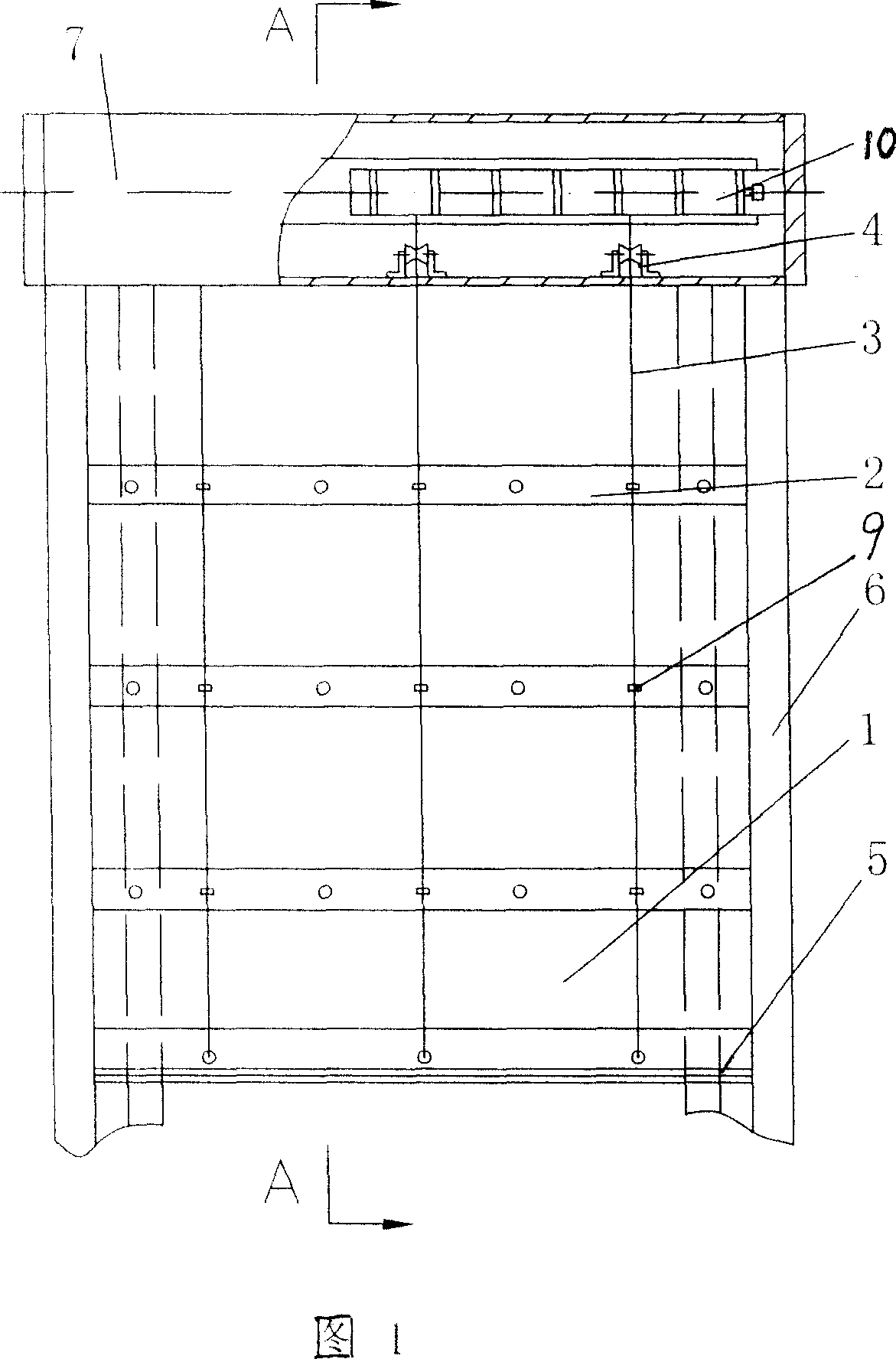
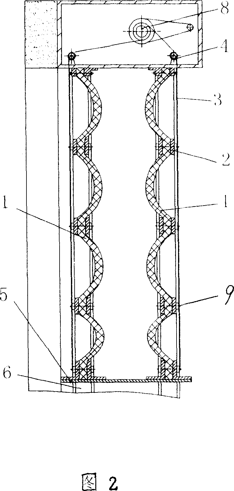
[0015] Door rolling machine 10 is arranged, and rolling door machine 10 places in the bag case 7, and the control circuit that door rolling machine 10, bag case 7 and join with rolling door machine 10 is all with prior art. A plurality of steel wire ropes 3 are vertically arranged in double rows, and screws with collars 9 fix a plurality of splints 2 (a pair) arranged at intervals in the transverse direction on the inorganic cloth-based curtain surface 1 with a fireproof interlayer in the middle. Face 1 is placed between splints 2 . The splint 2 at the top is fixedly connected to the bag box 7, the splint 2 at the bottom is fixed to the lower end of the steel wire rope 3 and a bottom plate 5 is connected between the two splints 2, and the collars 9 on the multiple splints 2 in the middle are set on the steel wire rope 3, and the steel wire rope 3 above is connected with the reel 8 of the door rolling machine 10 through the fi...
Embodiment 2
[0016] Embodiment 2 is as shown in Figures 1, 2, 3, and 4:
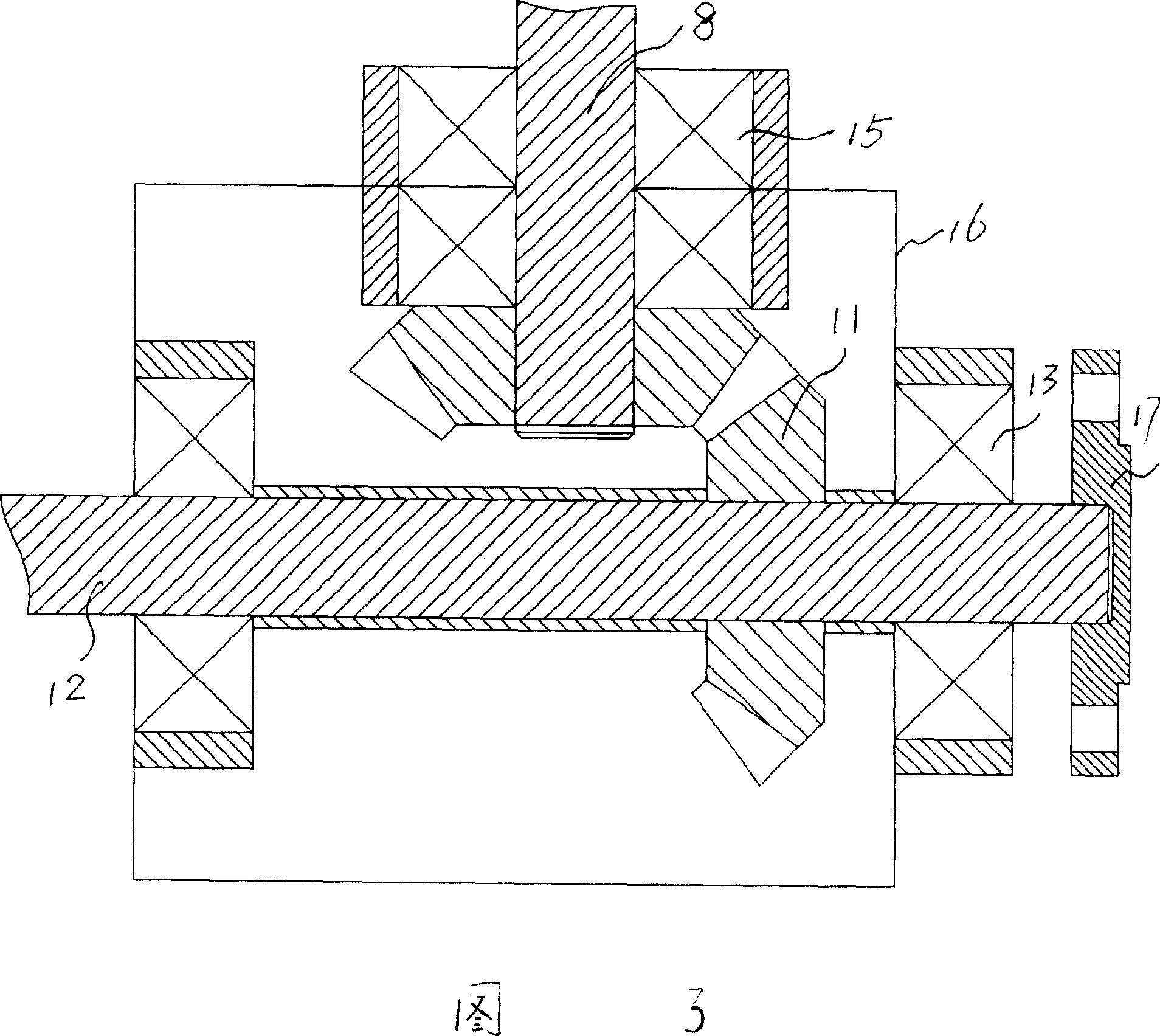
[0017] Other structures are all the same as in embodiment 1, except that the entire curtain surface is T-shaped, L-shaped or U-shaped, and the shape of the splint 2 can be determined according to the specific shape of the roller blind, and the connection mode of the splint 2 can be as shown in Figure 4. Screws 18 connect the segmented splints 2 . There can be multiple door rolling machines 10, so as to roll the wire ropes 3 on different planes. But the transmission mechanism shown in Figure 3 can also be used, that is, bevel gears 11 are connected to the two ends of the spool 8, the bevel gears 11 are connected to the spool 12 arranged on the bearing 13, and the bevel gear 11, the bearing 13 and the spool 8 connected bearings 15 are arranged on the gear box 16, flange 17 is connected on the end of the reel 12, during installation, the gear box 16 is fixed by the flange 17, and the wire rope 3 is connected with the r...
Embodiment 3
[0018] Embodiment 3 is as shown in Figures 1, 2, 3, and 4:
[0019] Other structures are with embodiment 1 or embodiment 2, and just splint 2, base plate 5 all are the annular of closure, as circle, square etc., because the splint 2 of closure does not have end, so need not guide rail 6.
[0020] work process:
[0021] When there is no fire, the steel wire rope 3 is rolled on the reel 8 of the rolling door machine 10 through the fixed pulley 4, and the bottom splint 2 connected to the lower end of the steel wire rope 3 is lifted along the guide rail 6 with the steel wire rope 3, and the multiple splints 2 in the middle are also lifted along the guide rail 6. The guide rail 6 slides and folds the inorganic cloth-based curtain surface 1. When the bottom splint 2 is lifted below the box 7, the rolling door machine 10 stops; Start, the top splint 2 is fixed, the bottom splint 2 descends along the guide rail 6 with the wire rope 3, the folded inorganic cloth-based curtain surface ...
PUM
 Abstract
Description
Claims
Application Information
 - R&D
- Intellectual Property
- Life Sciences
- Materials
- Tech Scout
- Unparalleled Data Quality
- Higher Quality Content
- 60% Fewer Hallucinations
Browse by: Latest US Patents, China's latest patents, Technical Efficacy Thesaurus, Application Domain, Technology Topic, Popular Technical Reports.
© 2025 PatSnap. All rights reserved.Legal|Privacy policy|Modern Slavery Act Transparency Statement|Sitemap|About US| Contact US: help@patsnap.com


