Lamp driver using solar cells

A solar power supply and driver technology, which is applied in the layout of electric lamp circuits, electric light sources, electrical components, etc., can solve problems such as energy loss, and achieve the effect of maintaining performance.

Inactive Publication Date: 2007-03-14
KONINK PHILIPS ELECTRONICS NV
View PDF0 Cites 110 Cited by
  • Summary
  • Abstract
  • Description
  • Claims
  • Application Information

AI Technical Summary

Problems solved by technology

Furthermore, since there are three conversion stages, there is considerable energy loss from the photovoltaic cell 11 to the lamp L

Method used


Image

  • Lamp driver using solar cells
  • Lamp driver using solar cells
  • Lamp driver using solar cells

Examples


Embodiment Construction

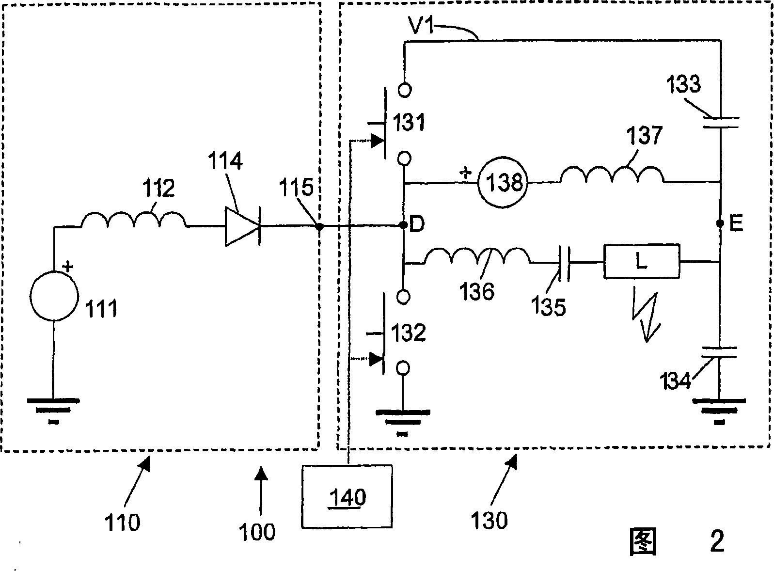
[0026] FIG. 2 schematically shows a block diagram of a first embodiment of a solar-powered lamp driver 100 according to the invention, comprising a boost stage 110 and a half-bridge inverter 130 .

[0027] The boost converter 110 includes at least one photovoltaic cell 111, an inductor 112 coupled at one end to the output of the photovoltaic cell 111 and at the other end to a rectifying element 114 (represented by a diode). A first terminal (in this case the anode), one terminal (in this case the cathode) of the rectifying element 114 is coupled to the output terminal 115 of the boost converter 110 .

[0028] The half-bridge inverter 130 comprises a first branch having two controllable switches 131 and 132 coupled in series between a first reference voltage V1 and a second reference voltage (mass); The node between the controlled switches 131 and 132 is marked D. The half-bridge inverter 130 comprises a second branch with two buffer capacitors 133 and 134 coupled in series be...


PUM


Abstract

A solar energy powered lamp driver (100; 200) capable of driving a gas discharge lamp (L) comprises: - a half-bridge inverter (130), comprising: a first branch of two controllable switches (131, 132) coupled in series between a first reference node (VI) and a second reference node (mass); a second branch of two buffer capacitors (133, 134) coupled in series between said first reference node (VI) and said second reference node (mass); an output branch (DE) connected between on the one hand a first node (D) between said two controllable switches (131, 132) and on the other hand a second node (E) between said two buffer capacitors (133, 134); a boost converter (110), having an output (115) connected directly to said first node (D) between said two controllable switches (131, 132).

Description

technical field [0001] The present invention generally relates to a lamp driver capable of driving a gas discharge lamp, in particular a high frequency gas discharge lamp, more particularly a high frequency TL lamp. More specifically, the present invention relates to lamp drivers capable of being powered by solar cells. Background technique [0002] Gas discharge lamps are generally known. In general, they consist of a luminous tube which seals the discharge vessel in a gas-tight manner, an ionizing filling and a pair of electrodes situated opposite each other within the discharge vessel, each electrode being connected to an associated electrical conductor which is delayed from the discharge vessel by the lamp vessel. to the outside. In operation, a voltage is applied across the electrodes creating a gas discharge between the electrodes causing a lamp current to flow between the electrodes. [0003] Discharge lamps are typically driven by electronic ballasts or drivers th...

Claims


Application Information

Patent Timeline
Patent Type & Authority Applications(China)
IPC IPC(8): H05B41/282H05B37/00
CPCH05B41/282H05B37/00Y02B20/00H05B47/10
Inventor M·A·M·亨德里西
Owner KONINK PHILIPS ELECTRONICS NV
Why Eureka
Try Eureka