Corona discharge type ionizer

An ion generator and corona discharge technology, applied in corona discharge devices, static electricity, circuits, etc., can solve problems such as difficulty in ion balance control, and achieve the effect of realizing interference signalization, low interference signalization, and simple structure

Inactive Publication Date: 2007-03-14
冈野一雄
View PDF0 Cites 9 Cited by
  • Summary
  • Abstract
  • Description
  • Claims
  • Application Information

AI Technical Summary

Problems solved by technology

[0008] However, the output voltage of the transformer is structurally not expressed on the output side even if an offset voltage is applied to the input side, so it is difficult to control the ion balance by applying the above-mentioned offset voltage.

Method used


Image

  • Corona discharge type ionizer
  • Corona discharge type ionizer
  • Corona discharge type ionizer

Examples


Embodiment Construction

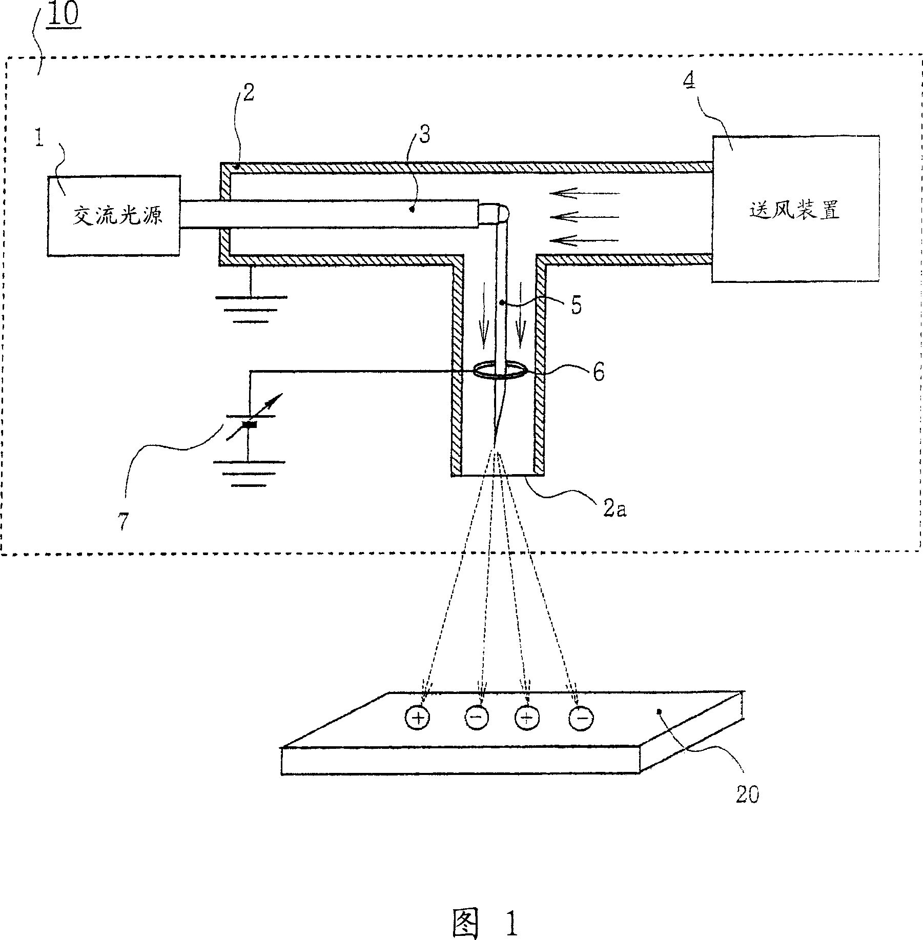
[0027] Hereinafter, preferred embodiments of the present invention will be described with reference to the drawings. FIG. 1 is a configuration diagram of a corona discharge type ion generator 10 of the present embodiment.

[0028] As shown in Figure 1, the corona discharge type ion generator 10 of the present embodiment comprises AC power supply 1, air supply pipe 2, voltage supply line 3, air supply device 4, emitter 5, control electrode 6, variable voltage supply part7. On the other hand, the corona discharge type ion generator 10 is a device for blowing ions to the object to be neutralized 20 to eliminate static electricity.

[0029] The AC power supply 1 , which is a voltage supply unit, applies a high voltage to the emitter 5 . This AC power supply 1 includes a transformer (not shown) in order to achieve a low-noise signal.

[0030] The air supply pipe 2 injects the compressed air pressurized and blown by the air supply device 4 from the air supply port 2a. And it is ...


PUM


Abstract

A corona discharge type ionizer having noise reduction realized by adding a highly effective ion balance function with a simple construction without making any special change in the construction to enable the use of a piezoelectric transformer. A corona discharge type ionizer (10) having a control electrode (6) disposed at a position which is in the cylinder of a blowing tube (2) serving also as a shield body and at which ion balance is established, wherein the ionizer satisfies 2Dc < Ds, where Dc is the cylinder inner diameter of the blowing tube (2) and Ds is the ring outer diameter of the control electrode (6).

Description

technical field [0001] The present invention relates to a corona discharge ion generator with ion balance control function. Background technique [0002] In the manufacturing process of electronic devices such as semiconductors (hereinafter referred to as electronic devices), once static electricity is generated on the electronic device, the electronic device will be damaged by static electricity due to high-voltage static electricity, or floating in the air. A failure in which particles are attracted to a semiconductor circuit of an electronic device to cause a short circuit in the semiconductor circuit (hereinafter, simply referred to as an electrostatic failure). Such electrostatic faults are one of the main reasons for lowering the manufacturing yield of electronic devices. [0003] This problem can be solved if the floating objects in the clean room can be completely removed, but it is practically difficult, so it is sought to solve it by removing the static electricit...

Claims


Application Information

Patent Timeline
Patent Type & Authority Applications(China)
IPC IPC(8): H05F3/04H01T19/04H01T19/00
CPCH01T19/00H01T19/04H01T23/00H03F3/04
Inventor 冈野一雄
Owner 冈野一雄
Why Eureka
Try Eureka