Exhaust gas treatment apparatus

a gas treatment apparatus and exhaust gas technology, applied in the direction of magnetic separation, machines/engines, electric supply techniques, etc., can solve the problems of increased pressure loss of gas treatment apparatus, insufficient agglomeration effect, and difficulty in manufacturing apparatus, so as to increase the pressure, and reduce the number of particulates.

Inactive Publication Date: 2011-03-31
NGK INSULATORS LTD
View PDF13 Cites 45 Cited by
  • Summary
  • Abstract
  • Description
  • Claims
  • Application Information

AI Technical Summary

Benefits of technology

[0015]The present invention has been made in order to solve the aforementioned problems of prior art and aims to provide an exhaust gas treatment apparatus capable of decreasing the number of the particulates contained in exhaust gas by agglomerating the particulate matter contained in the exhaust gas.
[0017][1] An exhaust gas treatment apparatus comprising: a tubular body functioning as a flow passage where exhaust gas passes, and a discharge electrode disposed in an central portion in a cross section perpendicular to a flow direction of the flow passage inside the tubular body and causing corona discharge in the vicinity thereof by applying a voltage; wherein the tubular body has a shape where an inner diameter of the tubular body is gradually reduced in a predetermined range from a face which contains a central point of generation of corona discharge generated by the discharge electrode and which is perpendicular to the flow passage toward the downstream side of the flow passage, and the number of particulates suspended in the exhaust gas is decreased by charging the particulate matter contained in the exhaust gas passing through the tubular body by corona discharge caused by the discharge electrode, collecting the charged particulate matter on an inner wall face of the tubular body by the electric field generated from the discharge electrode toward the inner wall face of the tubular body to agglomerate plural particulates, and allowing the agglomerated particulates to scatter again.
[0025]The exhaust gas treatment apparatus of the present invention can decrease the number of the particulates present in exhaust gas by agglomerating the particulate matter contained in exhaust gas. In particular, since an exhaust gas treatment apparatus of the present invention can decrease the number of the particulates even without disposing a filter or the like causing increase in pressure loss of the exhaust system, it can suitably be used as an exhaust gas treatment apparatus for treating exhaust gas discharged from a gasoline engine or the like where a harmful influence is caused by disposing a filter or the like causing increase in pressure loss.

Problems solved by technology

Such an exhaust gas treatment apparatus has a defect of increase in pressure loss because of complex flow passage constitution, and manufacturing of the apparatus is not easy.
In addition, since sufficient agglomeration effect cannot be obtained, the particulate matter passes through the apparatus and is released without being agglomerated.
Therefore, in the aforementioned constitution, there is a problem that the effect in agglomerating the particulate matter is small to be almost impossible to agglomerate the particulate matter practically.
Therefore, even in such a case, there is a problem that the effect in agglomerating the particulate matter is small to be almost impossible to agglomerate the particulate matter practically.
In particular, in a case that the exhaust gas flow rate is high or that the number of the particulates contained in exhaust gas is small, it is very difficult to trap the particulate matter on the inner wall face of the flow passage.
However, there is a problem that constitution of the electrode (the electrified portion and the agglomeration portion) is extremely complex to make it difficult to use it for an automobile or the like where large vibrations and the like are applied.
Therefore, there is a problem that the effect in agglomerating the particulate matter is small to be almost impossible to agglomerate the particulate matter practically.
In particular, since a gasoline engine has a low torque, if a filter increasing pressure loss of exhaust gas is disposed in an exhaust system, knocking is easily caused to cause an engine trouble or the like.
In addition, when a filter is disposed in an exhaust system of a gasoline engine to run over a long distance, deposition of ash derived from components contained in a gasoline of a fuel becomes a serious problem.
Since ash does not disappear even when high-temperature regeneration (burning) is performed in a filter unlike the PM, clogging is caused in the filter as a result to cause the increase in pressure loss.

Method used


Image

  • Exhaust gas treatment apparatus
  • Exhaust gas treatment apparatus
  • Exhaust gas treatment apparatus

Examples


example 1

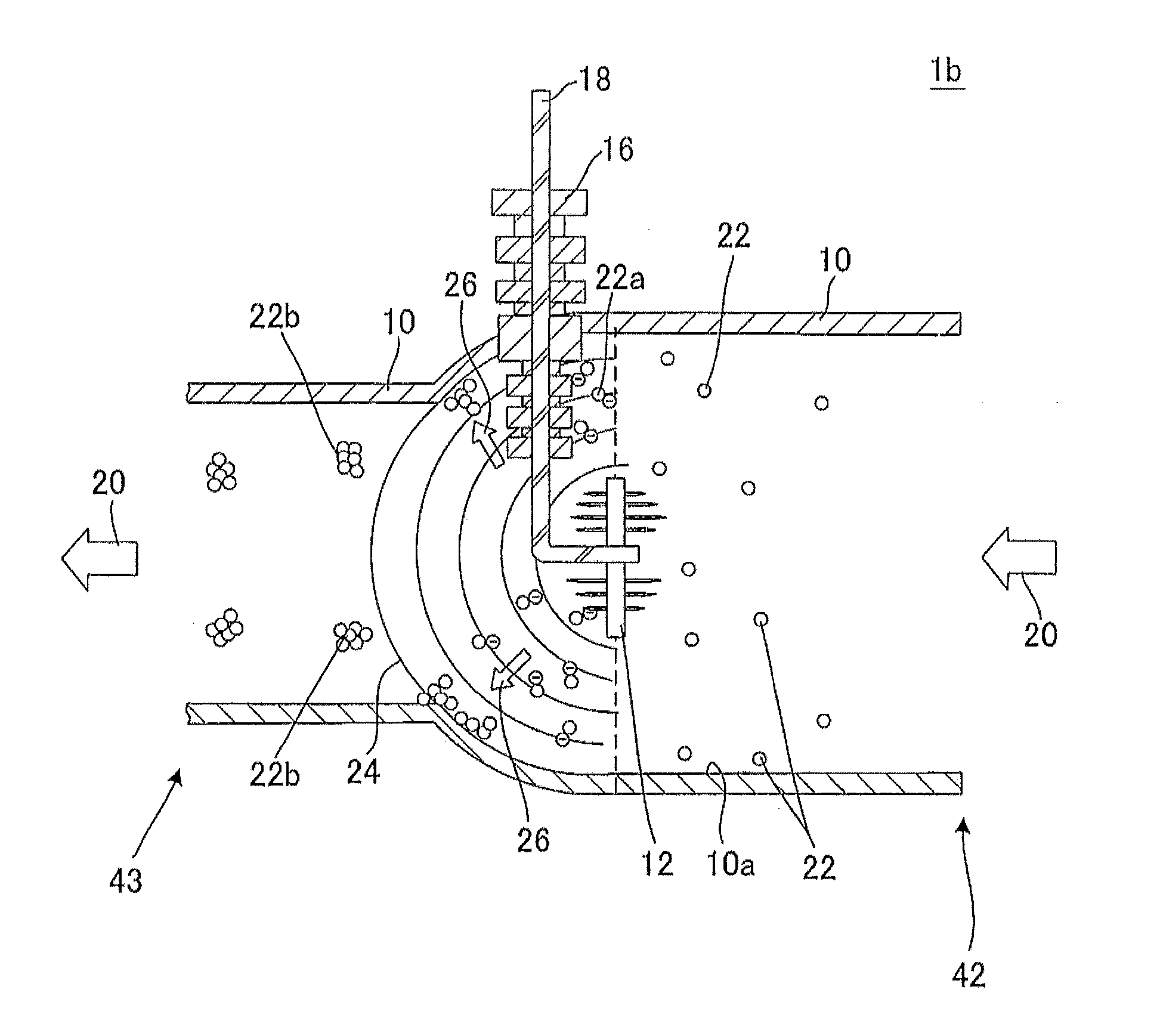
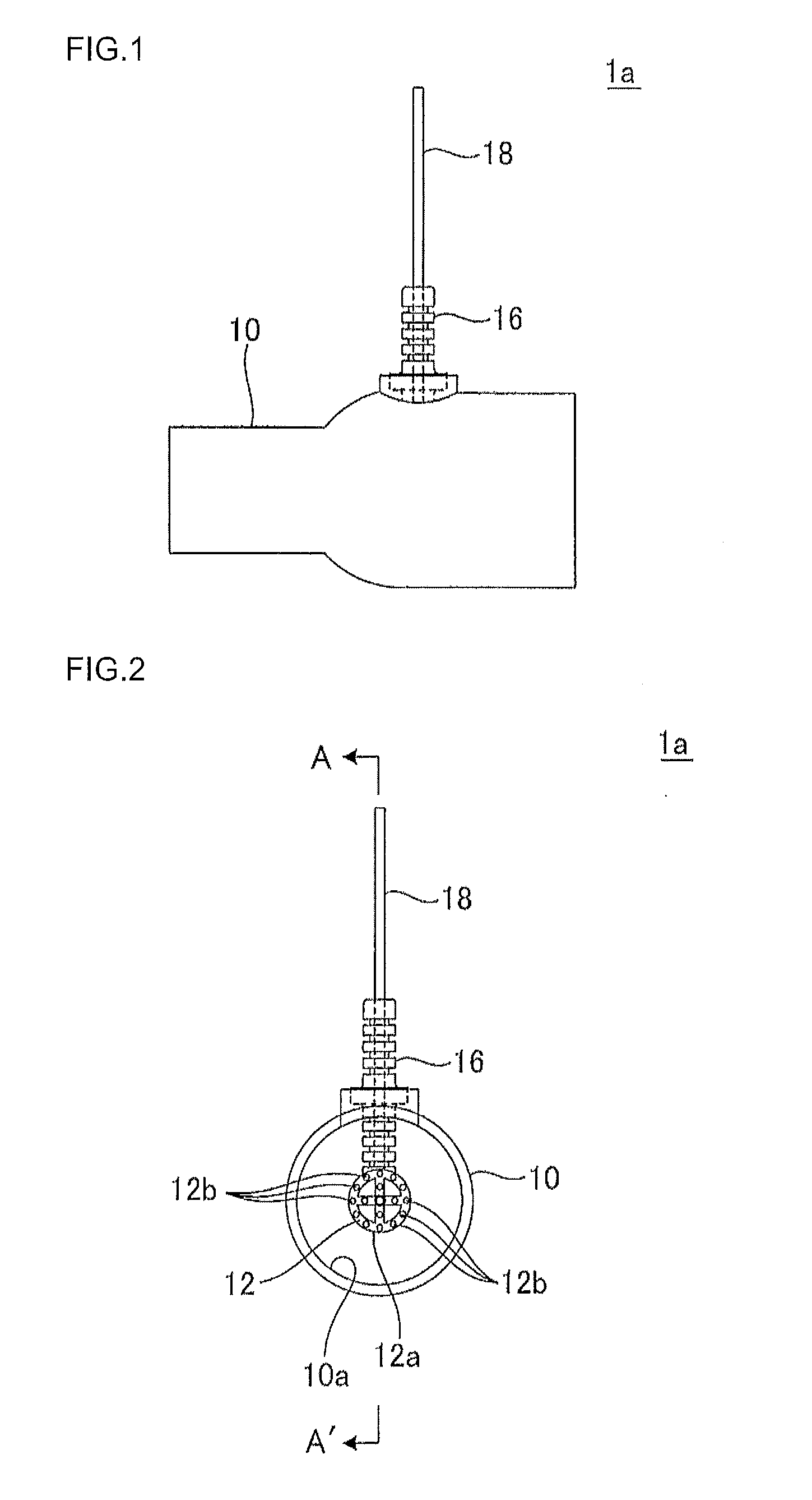
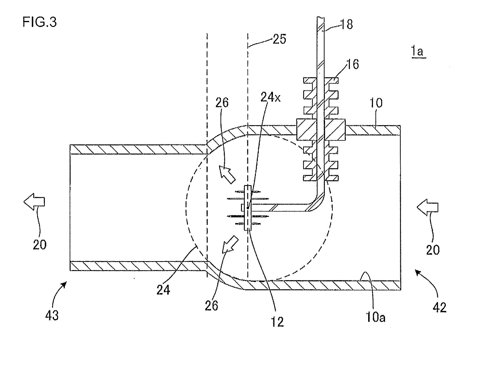
[0105]There was manufactured an exhaust gas treatment apparatus 1a as shown in FIGS. 1 to 3. The tubular body 10 had a circular cylindrical shape having a length of 300 mm in the exhaust gas flow direction, an outer diameter of 60.5 mm, and an inner diameter of 53.5 mm, and the material of the tubular body was stainless steel.

[0106]An alumina porcelain bushing 16 was disposed in the position of 30 mm from the end face on the upstream side of the flow direction of the tubular body 10 so that it passed through the tubular body 10, and a voltage introduction portion 18 was disposed inside the porcelain bushing 16. A discharge electrode 12 was connected to the voltage introduction portion 18 to fix the discharge electrode 12 inside the tubular body 10.

[0107]As shown in FIGS. 7 and 8, the discharge electrode 12 was constituted by the disc-like electrode support 12a and the 16 dischargers 12b (12 dischargers at an angle of 30° outside, and 4 dischargers at an angle of 90° inside) disposed...

example 2

[0129]There was manufactured an exhaust gas treatment apparatus constituted in the same manner as in Example 1 except that the inner diameter of the tubular body was formed to be generally reduced in the range from the face containing the central point of generation of corona discharge to the position of 20 mm toward the downstream side of the flow passage, and exhaust gas was treated in the same manner as in Example 1. The measurement results of the mass (g / hour) of particulate matter on the inlet side of the exhaust gas treatment apparatus and the number (×107 particulates / sec.), mass (g / hour), and average particle diameter (μm) of particulates on the outlet side during the exhaust gas treatment are shown in Table 2.

example 3

[0130]There was manufactured an exhaust gas treatment apparatus constituted in the same manner as in Example 1 except that the inner diameter of the tubular body was formed to be generally reduced in the range from the face containing the central point of generation of corona discharge to the position of 25 mm toward the downstream side of the flow passage, and exhaust gas was treated in the same manner as in Example 1.


PUM


Abstract

There is provided an exhaust gas treatment apparatus 1a including: a tubular body 10 and a discharge electrode 12 disposed inside the tubular body. The tubular body 10 has a shape where an inner diameter of the tubular body 10 is gradually reduced in a predetermined range from a face 25 which contains a central point 24x of generation of corona discharge 24 generated by the discharge electrode 12 and which is perpendicular to the flow passage toward the downstream side 44 of the flow passage.

Description

BACKGROUND OF THE INVENTION AND RELATED ART STATEMENT[0001]The present invention relates to an exhaust gas treatment apparatus. More specifically, the present invention relates to exhaust gas treatment apparatus capable of decreasing the number of the particulates present in exhaust gas by agglomerating the particulate matter contained in the exhaust gas.[0002]There is increased need to remove particulate matter and harmful substances in exhaust gas discharged from internal combustion engines such as automobile engines, construction machine engines; industrial machine stationary engines and other combustion burning appliances; and the like in consideration of influence on the environment. In particular, in recent years, the regulations regarding the removal of the particulate matter (hereinbelow sometimes referred to as “PM”) contained in exhaust gas have had a tendency to be strengthened on a global basis.[0003]As an exhaust gas treatment apparatus for treating exhaust gas containi...

Claims


Application Information

Patent Timeline
Patent Type & Authority Applications(United States)
IPC IPC(8): F01N3/01
CPCF01N3/01F01N3/0275B03C3/06B03C3/41B03C2201/30B03C3/70B03C2201/10B03C2201/12B03C3/49
Inventor TOKUDA, MASAHIROEGAMI, TAKASHISAKUMA, TAKESHIKONDO, ATSUO
Owner NGK INSULATORS LTD
Why Eureka
Try Eureka