
Knife holding net box for thin knift paper separator

A technology of clamping knives and cages, applied in the direction of machining/deformation, etc., can solve the problems of difficulty in discharging paper scraps, inconvenient maintenance, asynchronous and other problems, and achieve the effect of avoiding the phenomenon of knife collision.

Inactive Publication Date: 2007-03-21
GUANGDONG WANLIAN PACKAGING MACHINERY
View PDF2 Cites 0 Cited by
  • Summary
  • Abstract
  • Description
  • Claims
  • Application Information

AI Technical Summary

Problems solved by technology

[0010] The present invention aims at problems such as out-of-synchronization, collision of knives, difficulty in discharging paper scraps, high cost and inconvenient maintenance in the existing clamping plate, and designs a simple structure, low cost, convenient operation and effective avoidance of cutter damage faults. Cutter Cage for Thin Knife Slitter

Method used


Image

  • Knife holding net box for thin knift paper separator
  • Knife holding net box for thin knift paper separator
  • Knife holding net box for thin knift paper separator

Examples


Embodiment Construction

[0025] The specific implementation manner of the present invention will be described in detail below in conjunction with the accompanying drawings and the prior art.

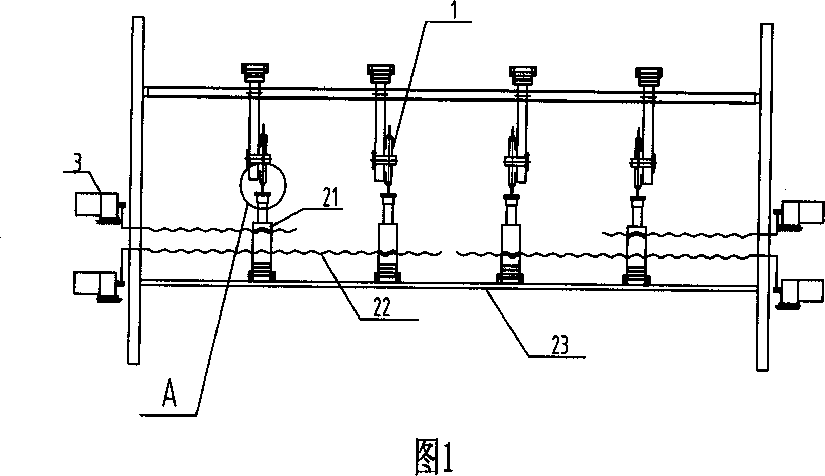
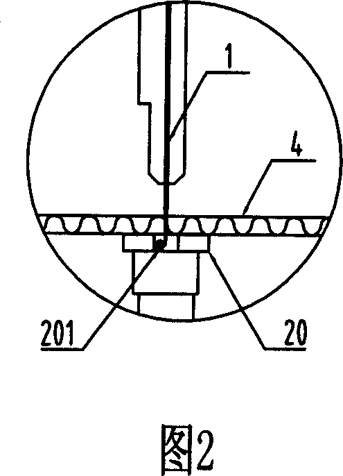
[0026] Fig. 1 shows the thin-knife paper separator of the prior art, and the bottom of each group of cutters 1 is simultaneously provided with a clamping plate 20, and the clamping plate 20 is connected on the lower knife seat 21, and the lower knife seat 21 is controlled by a screw rod 22. driven, and then controlled by the motor 3 to move left and right on the linear guide rail 23 and keep in sync with the cutter 1. Figure 2 is a partial enlarged structural diagram of the paper separator when separating paper, which is located on the clamping plate 20 directly below the cutter 1 There is a 3mm slot 201. When separating the paper, the cutter 1 falls into the slot 201 after separating the cardboard 4, which is a normal working state. However, because the size of the paper needs to be changed frequently, the posit...


PUM


Abstract

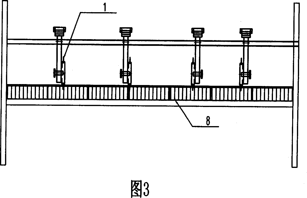
The present invention relates to knife holding mechanism for thin knife paper separator, and is especially one kind of knife holding net box for thin knife paper separator. The present invention features the knife holding net box comprising two side fixing boards and one middle support column. The fixing board has homogeneously arranged notches in the upper and lower ends, and inside the notches, there are embedded stainless steel wires tightened with spring. The notch spacing is 3-5 mm, and the stainless steel wires have diameter of 0.2-1 mm matching the notch width. The present invention has simple structure, low cost, convenient operation and less damage of the knife.

Description

technical field [0001] The invention relates to a knife-clamping mechanism of a thin-knife paper splitter, in particular to a knife-clamp net box used for a thin-knife paper splitter. Background technique [0002] At present, there are about three forms of clamping structure of the thin knife paper separator in the corrugated cardboard production line at home and abroad: [0003] 1. The clamping plate moves synchronously with the paper separator; [0004] 2. Nylon branch cylindrical knife roller; [0005] 3. Brush type steel wire clip cutter body. [0006] Most of the manufacturers that produce thin knife paper separators use the first form - the clamping plate. The specific structure is formed like this: the clamping plate is connected on the lower knife seat, and the lower knife seat is driven by the screw rod, and then the left and right movement is synchronized with the cutting knife through the control of the motor. There is a 3mm groove on the clamping plate. When ...

Claims


Application Information

Patent Timeline
Patent Type & Authority Applications(China)
IPC IPC(8): B31F1/20
Inventor 罗伟彬
Owner GUANGDONG WANLIAN PACKAGING MACHINERY
Learn More