Wefting inserter for air-jet loom
An air-jet loom and weft-inserting technology, which is applied in looms, textiles, textiles, and papermaking, can solve the problems of affecting the quality of wefts and hindering the high-speed air-jet loom, and achieve the effect of preventing twisting
- Summary
- Abstract
- Description
- Claims
- Application Information
AI Technical Summary
Problems solved by technology
Method used
Image

Examples
no. 1 approach
[0035] Hereinafter, a first embodiment will be described based on FIGS. 1 to 3 .
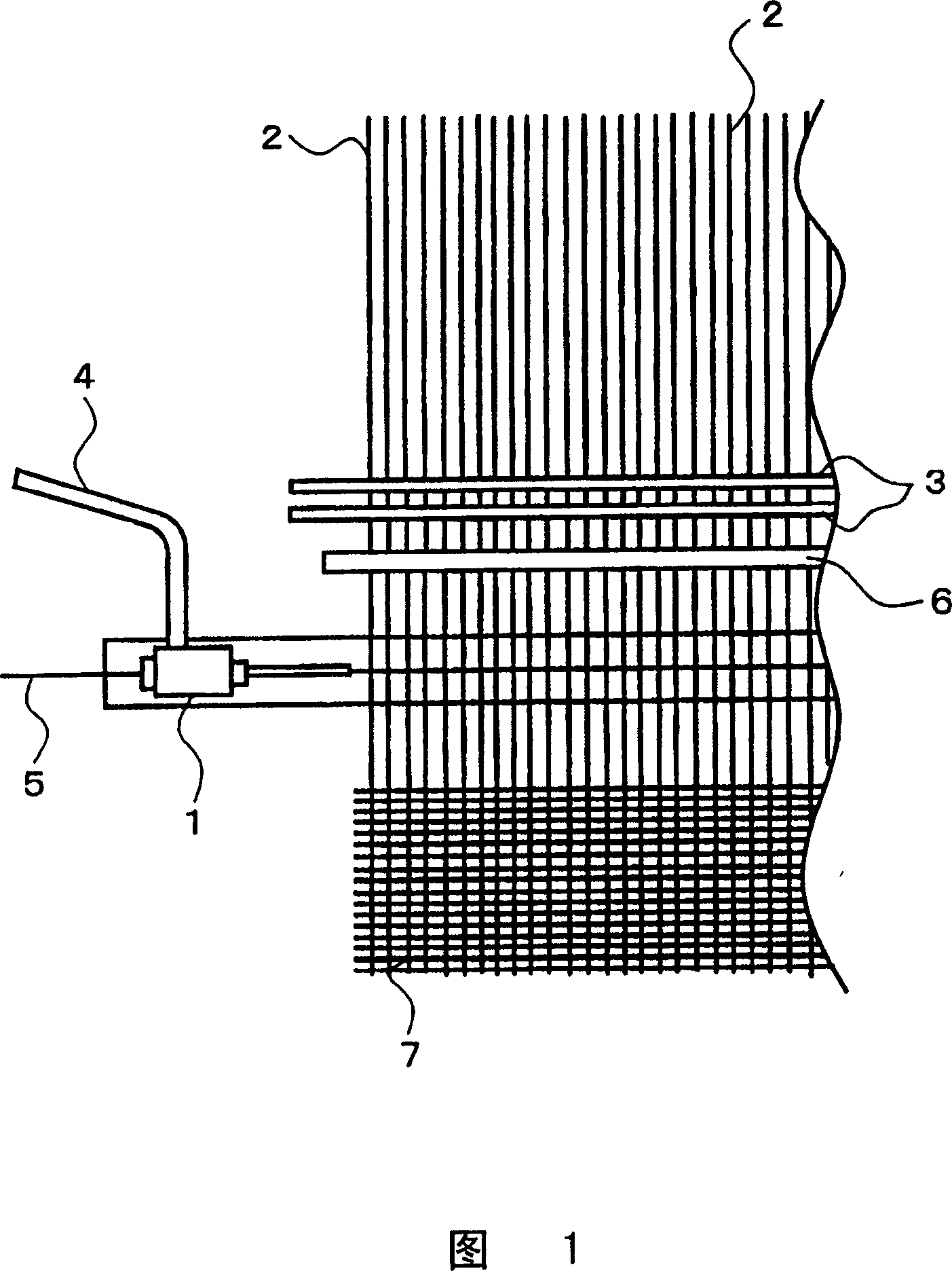
[0036] In FIG. 1, the arrangement|positioning position of the weft insertion nozzle 1 in the weft insertion device of an air-jet loom is shown. As is well known, the warp thread 2 sent out from the warp beam (not shown) is opened or closed by the heald frame 3 . The weft insertion nozzle 1 sprays the compressed air flow supplied from the unshown compressed air source through the switching rod and the pipe 4 during weft insertion, and penetrates the weft insertion through the unshown thread supply part through the weft thread length measurement and storage device. The weft threads 5 of the nozzle 1 are inserted into the warp thread openings. After the weft insertion is completed, the weft thread 5 is reeded by the reed 6 to form a woven cloth 7 .
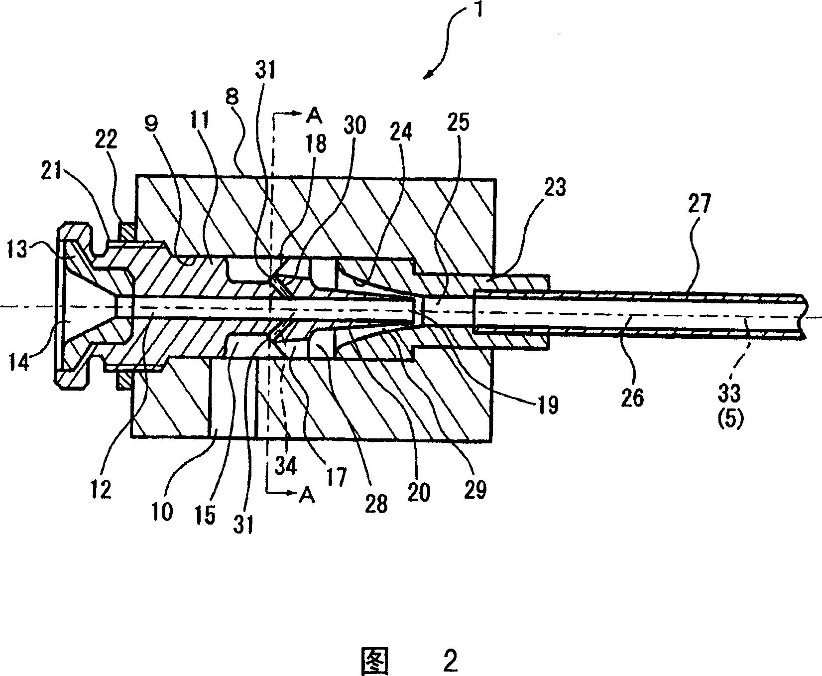
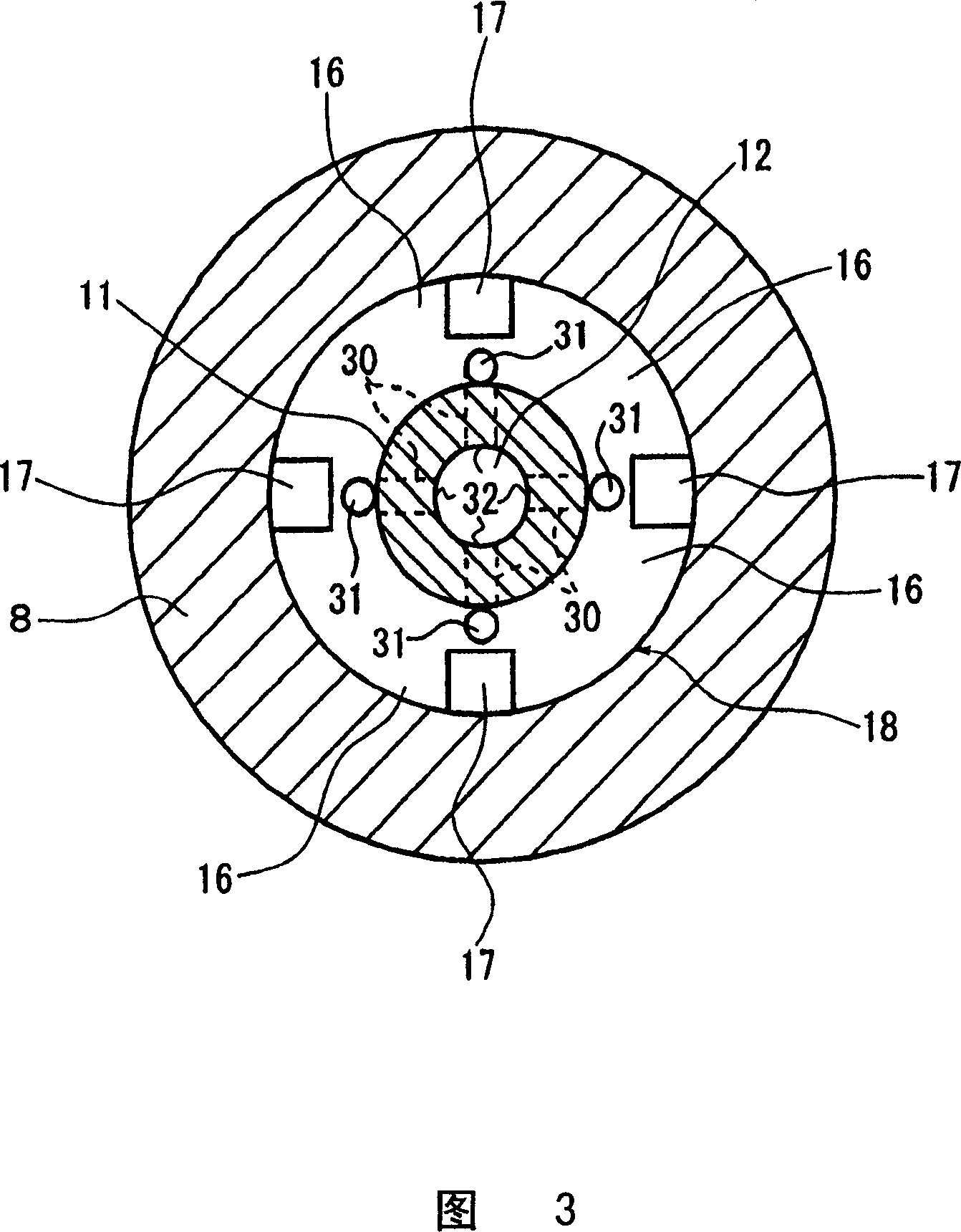
[0037] The detailed structure of the weft insertion nozzle 1 is shown in Figures 2 and 3. The nozzle body 8 has a hole 9 penetrating substantially ...
no. 2 approach
[0054] In the second embodiment shown in FIGS. 4 and 5 , the arrangement positions of the second injection passages in the first embodiment described above are changed. Therefore, the same reference numerals are given to the same components as in the first embodiment described above, and description thereof will be omitted.
[0055] The second injection passage 40 in the second embodiment is arranged on the rectification piece 16 constituting a part of the rectification member 18 . That is, as shown clearly in Fig. 5, the inlet 41 opening of the second injection passage 40 is present on the wall surface of the first annular chamber 15 side of the rectifying piece 16 existing between each rectifying passage 17, and is projected outward in the rectifying piece 16. After the weft direction is obliquely penetrated, the outlet 42 is opened in the weft passage 12 . Here, in the second injection passage 40 , the passage from the inlet 41 to the outlet 42 is formed by a tapered surfa...
no. 3 approach
[0059] The third embodiment shown in FIG. 6 is a modification of the second injection passage in the first embodiment described above. Therefore, the same reference numerals are given to the same components as in the first embodiment described above, and description thereof will be omitted.
[0060] The second injection passage 50 in the third embodiment is arranged at the same position as that in the first embodiment, and its inlet 51 is opened to the first annular chamber 15 , and its outlet 52 is opened to the weft passage 12 . However, the longitudinal central axis 53 of the second injection passage 50 and the longitudinal central axis 33 of the weft passage 12 are shifted by a predetermined amount so that they do not intersect. In addition, in the four second injection passages 50 shown in FIG. 6 , the longitudinal center axes 53 of the respective longitudinal direction central axes 53 are shifted in the rotational direction with respect to the longitudinal direction cent...
PUM
 Abstract
Description
Claims
Application Information
 - R&D
- Intellectual Property
- Life Sciences
- Materials
- Tech Scout
- Unparalleled Data Quality
- Higher Quality Content
- 60% Fewer Hallucinations
Browse by: Latest US Patents, China's latest patents, Technical Efficacy Thesaurus, Application Domain, Technology Topic, Popular Technical Reports.
© 2025 PatSnap. All rights reserved.Legal|Privacy policy|Modern Slavery Act Transparency Statement|Sitemap|About US| Contact US: help@patsnap.com