Sealing device for machines for thermal treatment of yarns

A technology of sealing head and fiber, applied in the field of textile industry, can solve the problem of no longer use

Inactive Publication Date: 2007-03-21
SUPERBA SAS
View PDF3 Cites 1 Cited by
  • Summary
  • Abstract
  • Description
  • Claims
  • Application Information

AI Technical Summary

Problems solved by technology

The sealing problem of rollers so arranged is different from that encountered with rollers stacked on top of each other, and the corresponding solutions can no longer be used in this configuration of stacked rollers

Method used


Image

  • Sealing device for machines for thermal treatment of yarns
  • Sealing device for machines for thermal treatment of yarns
  • Sealing device for machines for thermal treatment of yarns

Examples


Embodiment Construction

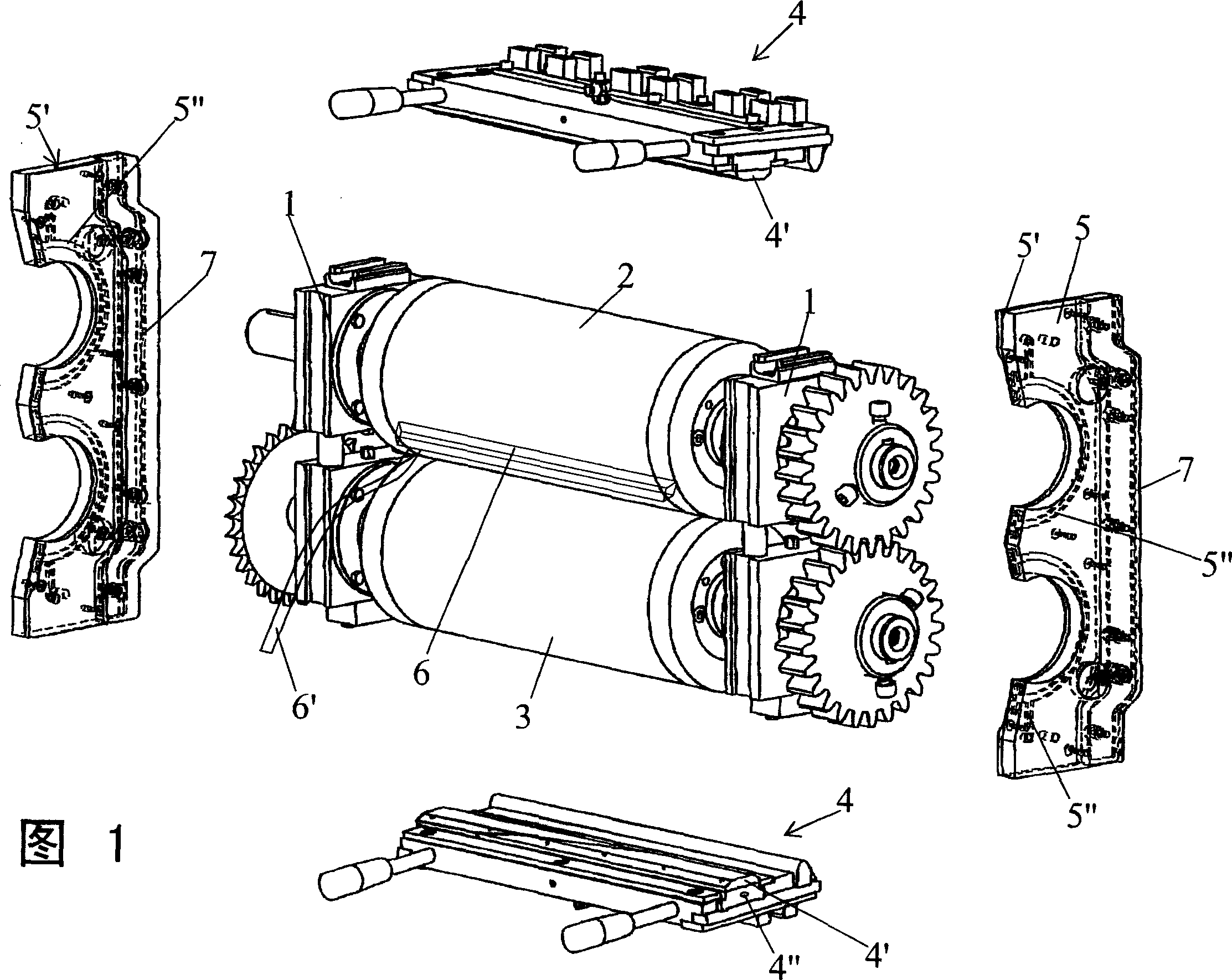
[0016] Figure 1 shows by way of example a sealing head for a fiber heat treatment machine, which mainly includes: a frame 1, which is fixed to a pressurized chamber (not shown) traversed by a conveyor belt (not shown); a pair of upper and lower Superposed horizontal rollers 2 and 3, which push against the opposite surfaces of the conveyor belt; sealing means 4 and 5, which form a sealed closed cavity between the rollers 2, 3 and the frame 1 . At least one horizontal roller 2 and the sealing means 4 and 5 are connected to actuators (not shown in detail) for corresponding movements. The frame 1 , which does not form part of the invention, is only represented by two transverse uprights, which serve to receive the rollers 2 and 3 .

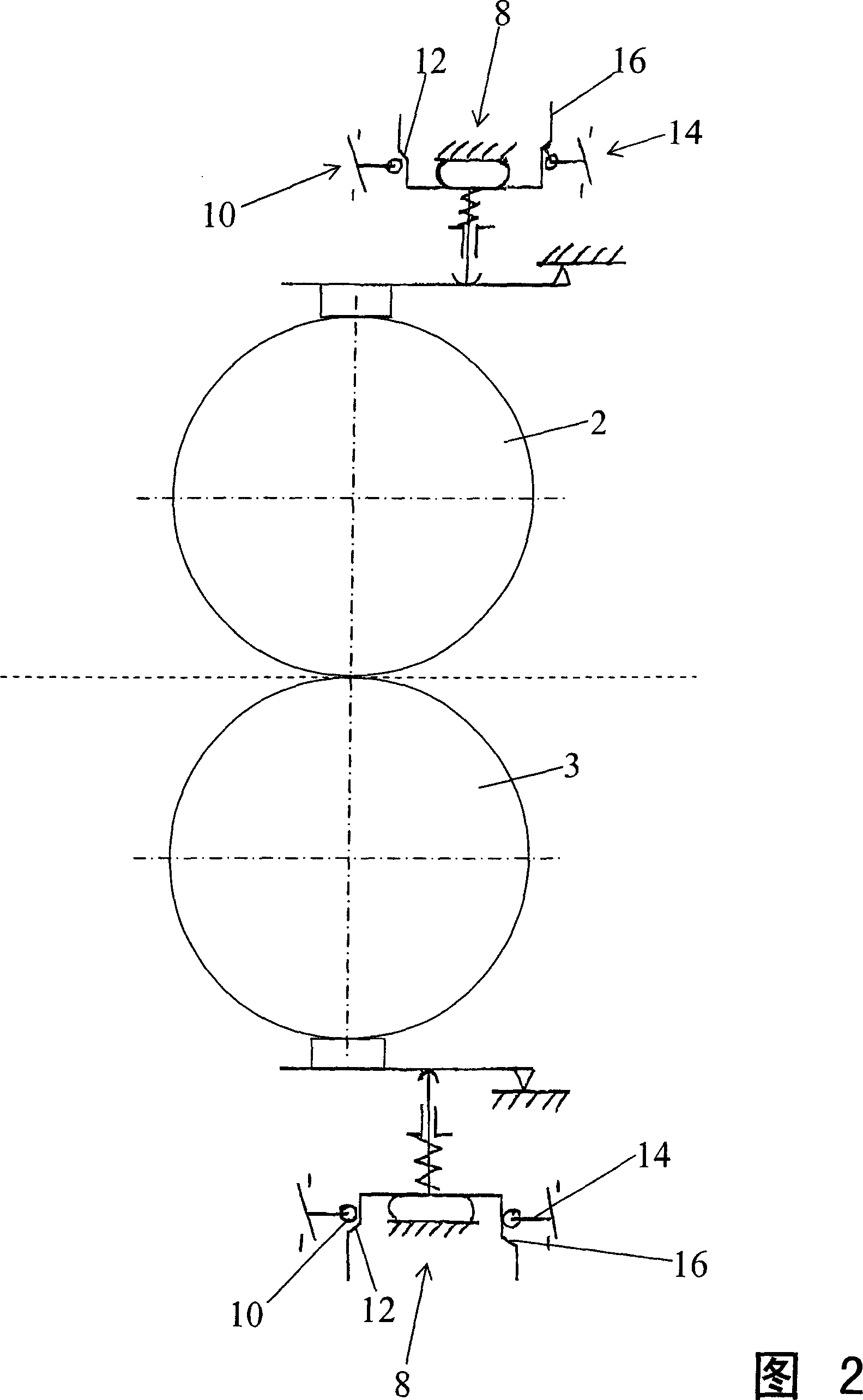
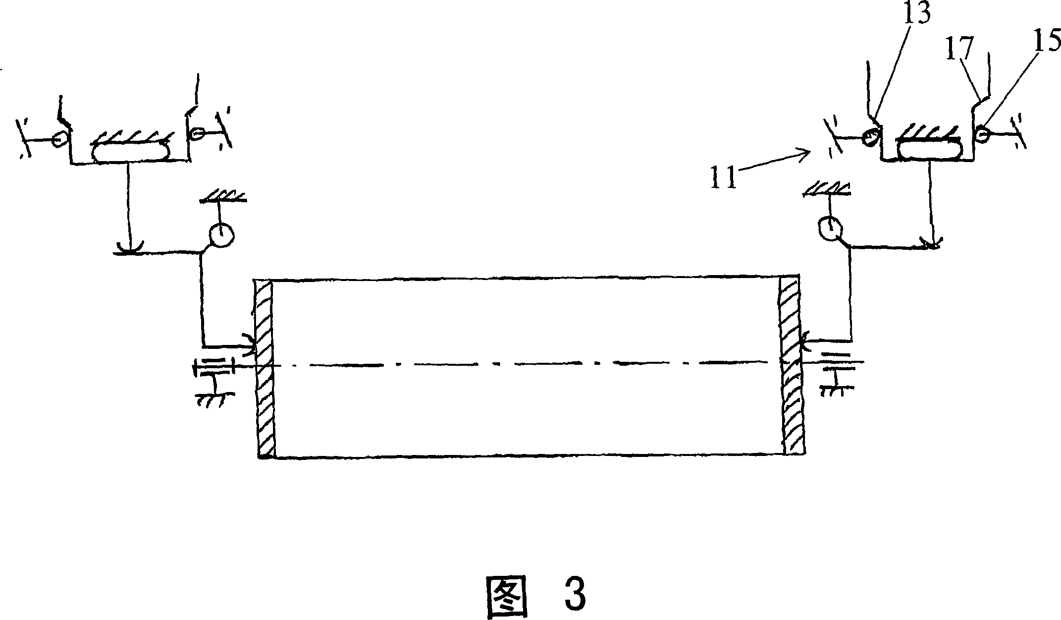
[0017] Furthermore, as shown in FIGS. 2 and 3 , the sealing means 4 and 5 are applied under pressure on the respective surfaces of the rollers 2 and 3 by means of actuators 8 and 9 comprising cylinders. Said cylinders act on the one hand on the seali...


PUM


Abstract

A sealing head for machines for the thermal treatment of filaments, includes a frame ( 1 ) fixed to a pressurized chamber traversed by a conveyor belt, a pair of superposed horizontal rollers ( 2 and 3 ), which are pressed against opposite surfaces of the conveyor belt, and sealing elements ( 4 and 5 ) to form a sealed closure between the rollers ( 2 and 3 ) and the frame ( 1 ). The sealing elements ( 4 and 5 ) to form a sealed closure between the rollers ( 2 and 3 ) and the frame ( 1 ) are each provided with integrated lubricating elements ( 4', 5 '), under pressure or by capillarity. The invention is more particularly applicable to the field of the textile industry, in particular the treatment of filaments by thermal treatment machines presently called thermofixation meachines.

Description

technical field [0001] The present invention relates to the field of the textile industry, and in particular to the treatment of fibers by means of heat treatment machines, now known as heat setting machines, in particular their sealing heads, and sealing heads for this purpose. Background technique [0002] A fiber heat treatment machine mainly comprises a pressurized chamber for the heat treatment of textile fibers arranged on a conveyor belt moving through said pressurized chamber, said chamber being closed at its two ends by sealing heads. Each sealing head consists of: a frame, which is fixed to the pressurized chamber; a pair of horizontal rollers, which are stacked on top of each other or approach each other in a horizontal plane, the rollers push on the opposite surface of the conveyor belt and ensure that the material can be driven and a conveyor belt; a sealing device forming a sealed closed cavity between the rollers and the frame. [0003] In one known machine o...

Claims


Application Information

Patent Timeline
Patent Type & Authority Applications(China)
IPC IPC(8): D06B23/18
CPCD06B23/18D06B23/16
Inventor 安托万·霍霍尔于贝尔·利布曼
Owner SUPERBA SAS
Why Eureka
Try Eureka