
Vehicle air throttle air inflow test system and testing method

A throttle body and testing system technology, applied in mass flow measurement devices, indirect mass flow meters, fluid flow detection using thermal effects, etc., can solve problems such as uneconomical and inconvenient, high process requirements, complex structure, etc., and achieve convenience The effect of low purchase and comprehensive cost and simple test structure

Inactive Publication Date: 2007-03-21
BYD CO LTD
View PDF0 Cites 7 Cited by
  • Summary
  • Abstract
  • Description
  • Claims
  • Application Information

AI Technical Summary

Problems solved by technology

Although this method has the advantages of high precision and good repeatability, but the structure is complex, and when measuring the air leakage (about 0.5g / s) of the fully closed idle channel, it is necessary to use the flow rate less than 0.1g / s under critical conditions. Nozzles, because this kind of nozzles require high technology and are expensive, there are few manufacturers in China
Therefore, for general automobile manufacturers or other non-throttle body manufacturers who need to detect the air intake of the throttle body, it is neither economical nor convenient to use this method.

Method used


Image

  • Vehicle air throttle air inflow test system and testing method
  • Vehicle air throttle air inflow test system and testing method

Examples


specific Embodiment 1

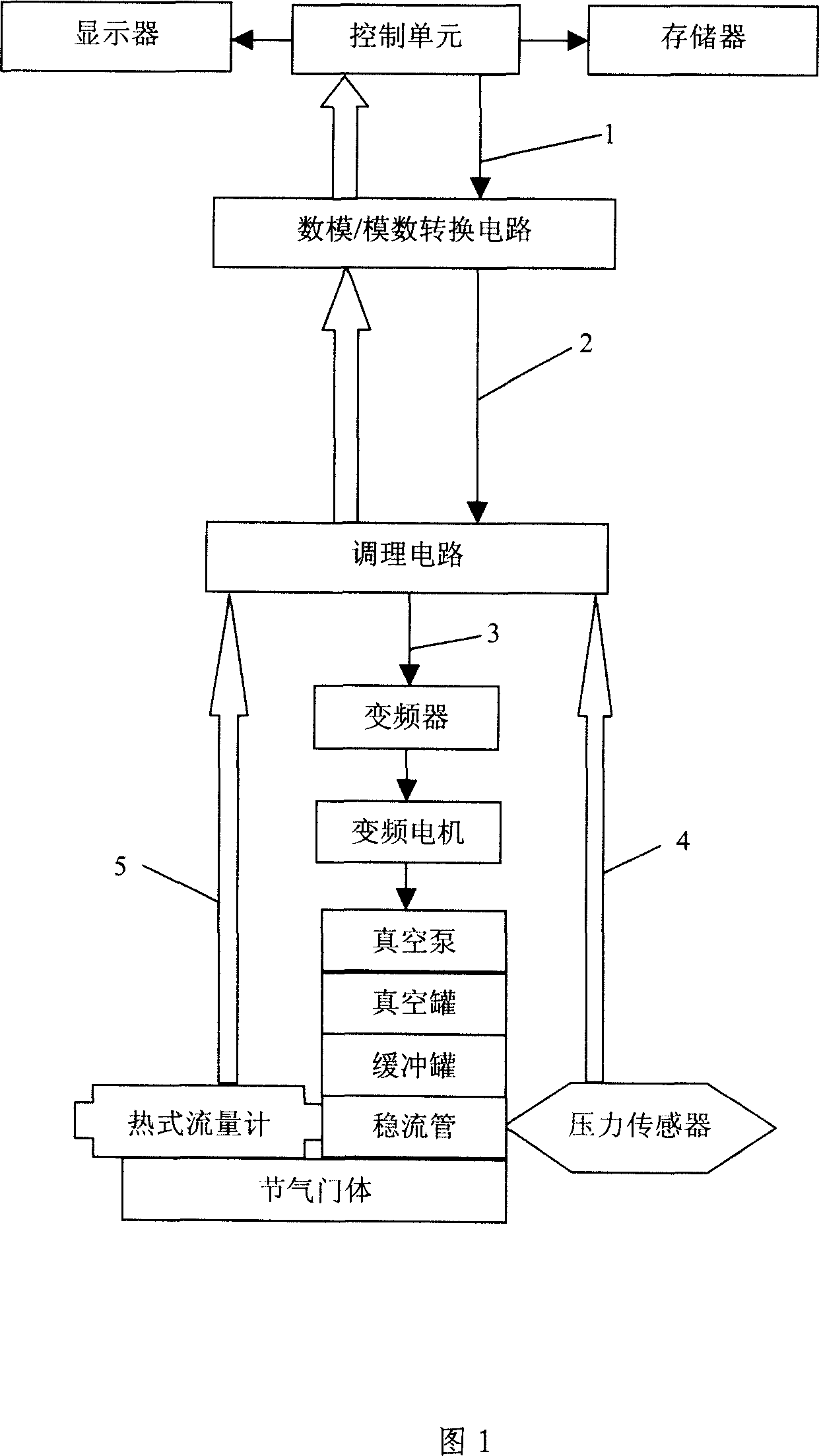
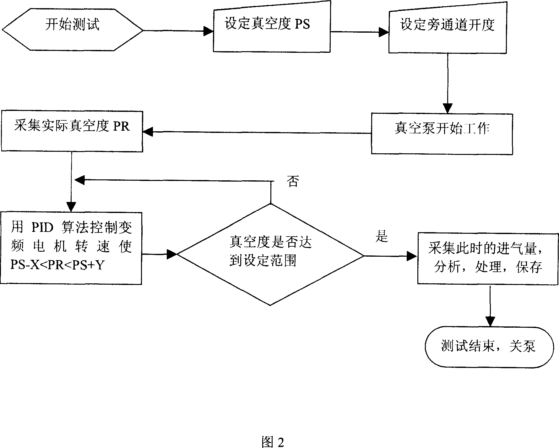
[0030] Specific embodiment one, as shown in Fig. 1, this testing system comprises vacuum source, pressure sensor, thermal gas flowmeter, also comprises the conditioning circuit connected in sequence, analog-to-digital / digital-to-analog conversion circuit and control unit, and vacuum source comprises gas Guide chamber, vacuum pump, variable frequency motor and frequency converter. The gas diversion cavity is connected with the air outlet of the throttle body, the frequency converter is electrically connected with the conditioning circuit, and responds to the control signal of the control unit. . The function of the conditioning circuit is to amplify and filter the passed analog signal. The pressure sensor and the thermal gas flowmeter are also respectively electrically connected to the conditioning circuit. The pressure sensor is arranged in the gas guiding cavity and is used for measuring the vacuum degree in the gas guiding cavity. The thermal gas flowmeter is also arrange...

specific Embodiment 2

[0053] Specific embodiment two, different from embodiment one, is that it is difficult to stabilize the actual vacuum degree when the vacuum degree adjustment is around the set vacuum degree and fluctuates greatly, it may be considered to add a buffer tank in the gas diversion chamber, A buffer tank is connected between the tank and the steady flow tube. The buffer tank is conducive to stabilizing the vacuum degree in the gas diversion chamber within the error range of the set vacuum degree. The buffer tank can be one or connected in series one by one. Multiple, until the vacuum degree in the steady flow tube can be stabilized within the error range of the set vacuum degree.

[0054] The present invention can not only be used for testing the gas mass flow rate of different opening degrees of the bypass channel of the automobile throttle body, but also can test the gas mass flow rate of different opening degrees of the main channel. In addition to detecting the intake air volum...


PUM


Abstract

The invention discloses an air input testing system and testing method of the motor car air throttle which includes the vacuum source, the pressure sensor, the thermal gas flowmeter and the control unit. The vacuum source includes the air guiding hollow connected with the air vent of the throttle which provides the vacuum condition for the air vent; the control unit can keep the vacuum degree in a stable error range and collect the flow rate signal outputted by the thermal gas flowmeter and compute the air flow according to the airflow sectional area. The invention can measure the air flow directly and has the simple structure and low cost.

Description

【Technical field】 [0001] The invention relates to a bench test system and a test method for the intake air volume of a throttle body under different working conditions in an automobile air intake system, in particular to the test of the air intake volume of a throttle body under the conditions of different openings of bypass passages during simulating vehicle idling systems and test methods. 【Background technique】 [0002] At present, most throttle body manufacturers mainly use the method of measuring the gas flow rate with a sonic nozzle when performing a bench test on the intake air volume of the throttle body. Although this method has the advantages of high precision and good repeatability, but the structure is complex, and when measuring the air leakage (about 0.5g / s) of the fully closed idle channel, it is necessary to use the flow rate less than 0.1g / s under critical conditions. Nozzles, because this kind of nozzles require high technology and are expensive, there are...

Claims


Application Information

Patent Timeline
Patent Type & Authority Applications(China)
IPC IPC(8): G01F1/86G01F1/68
Inventor 吴萌
Owner BYD CO LTD
Learn More