
Insulating coated wire and its producing method, insulating coated wire product and its producing method

A technology of insulating coatings and wires, which is applied in coil manufacturing, insulated conductors, insulated cables, etc., can solve the problems of easy generation of air holes, high cost, and difficulties, and achieve the goal of improving adhesion, preventing cost increases, and preventing insulation properties worsening effect

Active Publication Date: 2007-03-21
SANCALL CORP
View PDF0 Cites 2 Cited by
  • Summary
  • Abstract
  • Description
  • Claims
  • Application Information

AI Technical Summary

Problems solved by technology

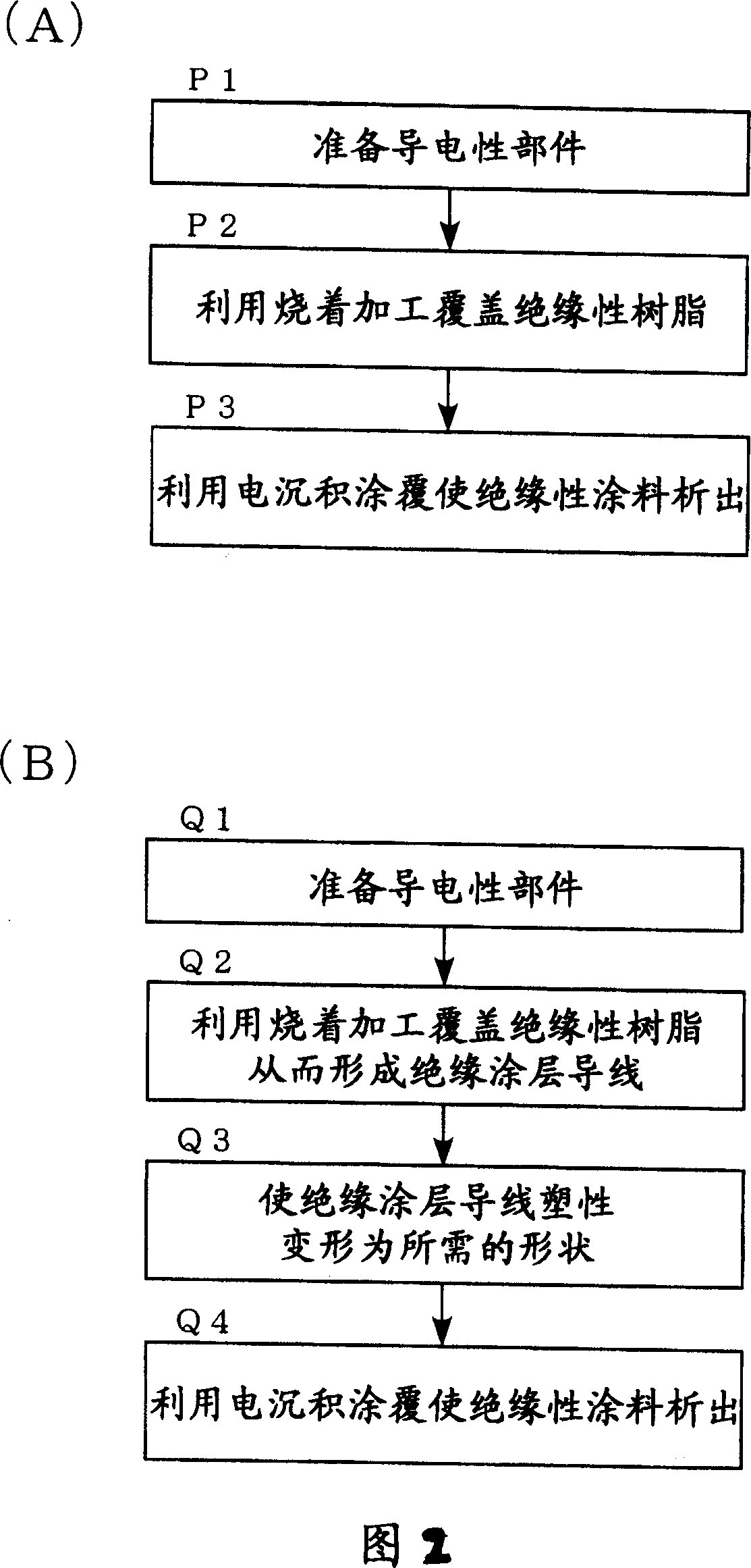
[0003] The above-mentioned firing process is effective in terms of cost in small-volume production, but on the other hand, there are disadvantages, such as when it is necessary to plastically deform an insulating-coated wire covered with an insulating resin into a desired shape, etc. Next, as shown in FIG. 7, during the above-mentioned plastic deformation processing performed after the above-mentioned firing processing, the above-mentioned insulating resin 12 peels off, and a part of the conductive member 11 is exposed, so that so-called pores P are likely to occur.
[0004] On the other hand, since the above-mentioned electrodeposition coating can be carried out after the plastic deformation process is performed on the conductive member, there will be no disadvantages such as the above-mentioned pores during the plastic deformation process, but on the other hand, in small-lot production the problem of high cost
[0005] In addition, when the above-mentioned plastic deformation processing is such that the above-mentioned conductive members are in close contact, the electrode deposition of the insulating paint on the close contact part can be realized by setting the gap to the necessary minimum, but it is relatively difficult.

Method used


Image

  • Insulating coated wire and its producing method, insulating coated wire product and its producing method
  • Insulating coated wire and its producing method, insulating coated wire product and its producing method
  • Insulating coated wire and its producing method, insulating coated wire product and its producing method

Examples


Embodiment Construction

[0038] Embodiments of the present invention will be described below with reference to the drawings.

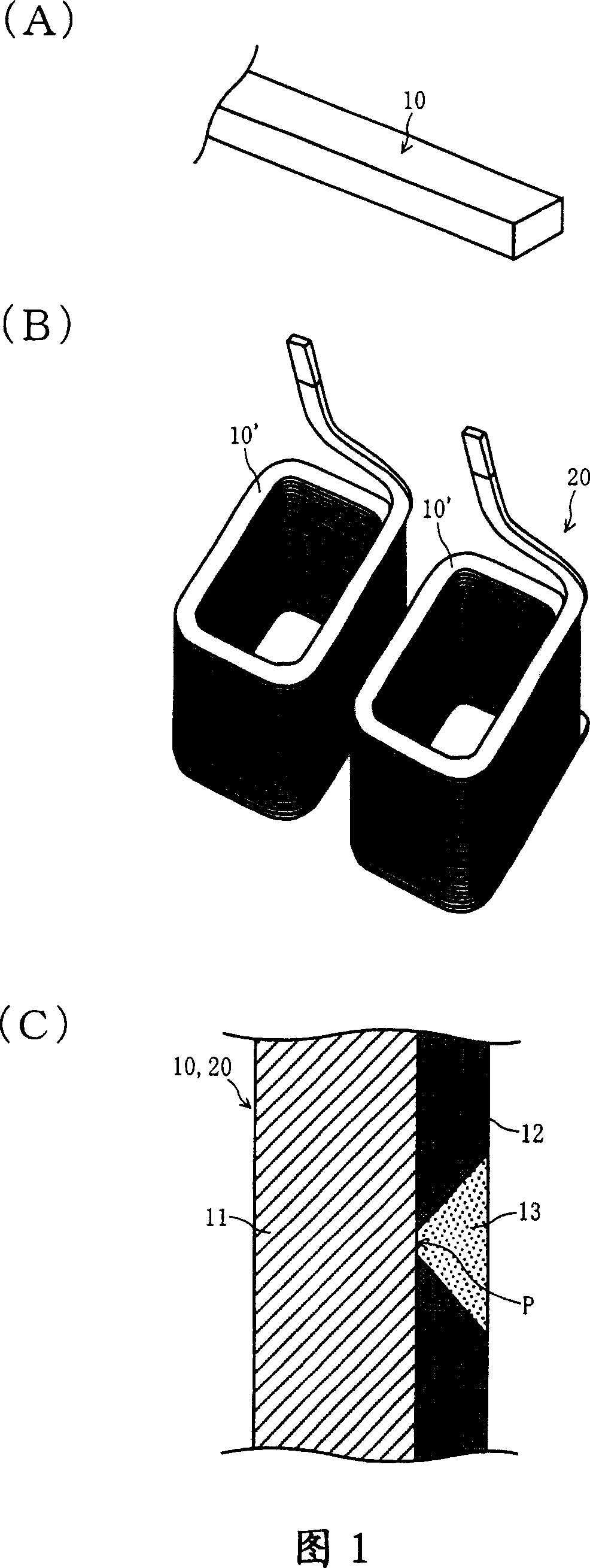
[0039]FIG. 1 is a diagram showing an insulating-coated wire 10 and an insulating-coated wire molded product 20 according to the present embodiment. FIG. 1(A) is a schematic perspective view of the above-mentioned insulating-coated wire 10, FIG. 1(B) is a schematic perspective view of the above-mentioned insulating-coated wire molded product 20, and FIG. 1(C) is a partial enlarged cross-section of the insulating-coated wire. The figure shows that in the insulating coated wire 10 shown in FIG. 1(A) and the insulating coated wire molded product 20 shown in FIG. 1(B), the insulating paint 13 is provided on the coated wire by electrodeposition coating The state on the peeled portion P of the insulating resin 12 of the conductive member 11 .

[0040] The above-mentioned insulating-coated wire 10 has: a conductive member 11, an insulating resin 12 coated on the above-mentioned condu...


PUM


Abstract

To provide an insulation coated conductor, where cost increase of small-lot production is avoided and the deterioration of an insulating property due to occurrence of pinholes can be prevented effectively, and provide an insulation coated conductor mold product and its manufacturing method. The insulation coated conductor provided a conductive member 11, insulating resin 12 coated with the conductive member 11 by a burning process, and an insulating coating material 13 which is electrodeposited on a peeled part P of the insulating resin 12, and its manufacturing method, in which the conductive member 11 is coated with the insulating resin 12 by a burning process, a peeled part P where the conductive member 11 is exposed is coated by the insulating coating material 13 in electrodeposition coating, are provided.

Description

technical field [0001] The present invention relates to an insulating-coated wire formed by coating an insulating resin on a conductive member by firing processing and a manufacturing method thereof, and an insulating wire obtained by plastically deforming the above-mentioned insulating-coated wire into a desired shape. Coated wire formed article and its manufacturing method. Background technique [0002] As a method of coating an insulating member on a conductive member, there is known a firing process in which an insulating resin is coated on a conductive member by dipping or spraying, and then fired to coat the conductive member. The method of processing, and the electrodeposition coating method of coating an insulating paint on a conductive member by electrodeposition processing. [0003] The above-mentioned firing process is effective in terms of cost in small-volume production, but on the other hand, there are disadvantages, such as when it is necessary to plastically...

Claims


Application Information

Patent Timeline
Patent Type & Authority Applications(China)
IPC IPC(8): H01B7/00H01B13/06H01F5/00H01F27/28H01F41/04
Inventor 村上隆夫
Owner SANCALL CORP
Learn More