Motorcycle brake oil pipe device

A technology for motorcycles and oil pipes, which is applied to vehicle parts, bicycle accessories, transportation and packaging, etc., can solve the problems of narrowing the available range, affecting the use of the first oil pipe 241, and having a small range.

Inactive Publication Date: 2007-03-28
KYMCO
View PDF0 Cites 6 Cited by
  • Summary
  • Abstract
  • Description
  • Claims
  • Application Information

AI Technical Summary

Problems solved by technology

[0004] However, it can be seen from the above description that the conventional motorcycle brake oil pipe device 2 has not been considered in the actual operation or assembly for the following problems:
[0005] 1. The oil pipe is easy to be pulled and squeezed: since the connecting pipe body 11 is arranged on the front end face of the triangular platform 14 facing forward, when the handle bogie 16 is turned, the first oil pipe 241 is easily pulled and extrusion, which affect the use of the first oil pipe 241, and even cause damage to the first oil pipe 241
[0006] 2. Oil pipes are difficult to configure: because the range between the connecting pipe body 21 of the motorcycle brake oil pipe device 2 and the front wheel 11 can be used to configure the second and third oil pipes 251, 261 is not large, and the mudguard The plate 15 also needs to be located in this space. In addition, the structure of the motorcycle brake oil pipe device 2 is relatively complicated and uses many components, which leads to a large occupation volume and greatly reduces the usable range of this part. It is very difficult to configure this part. The second oil pipe 251 and the third oil pipe 261
[0008] Although the motorcycle brake oil pipe device 3 makes its occupied volume smaller by simplifying its components, it can only slightly reduce the impact caused by the above-mentioned second problem. Moreover, the three-way pipe body 30 is still designed On the front end face of the triangular platform 14, the above-mentioned first problem still occurs, that is, the first oil pipe 311 is pulled.

Method used


Image

  • Motorcycle brake oil pipe device
  • Motorcycle brake oil pipe device
  • Motorcycle brake oil pipe device

Examples


Embodiment Construction

[0023] The foregoing and other technical contents, features and functions of the present invention will be clearly presented in the following detailed description of two preferred embodiments with reference to the drawings.

[0024] Before the present invention is described in detail, it should be noted that in the following description, similar elements are denoted by the same numerals.

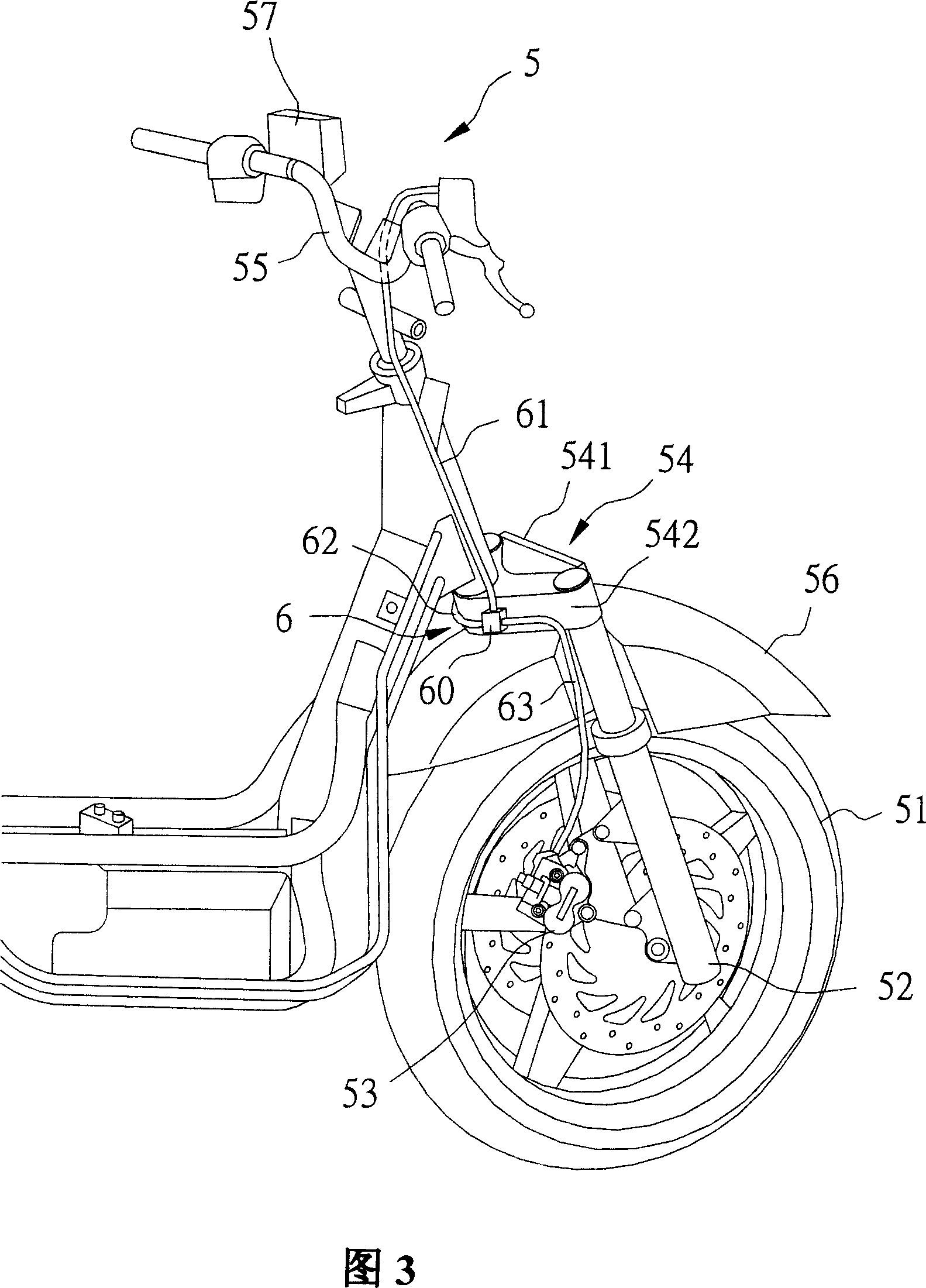
[0025] As shown in Figures 3 and 4, a first preferred embodiment of the motorcycle brake oil pipe device of the present invention is installed on a motorcycle front wheel steering device 5 to transmit brake fluid. The front wheel steering device 5 of the motorcycle comprises a front wheel 51, two shock absorbers 52 which are arranged on both sides of the front wheel 51 and can slow vibrations, and two respectively connect each shock absorber 52 and are positioned at each shock absorber 52 The disc brake unit 53 that can brake the front wheel 51 at the rear, a triangle platform 54 that connec...


PUM


Abstract

The invention is a motorcycle brake oil pipe device, equipped on a front wheel steering device of a motorcycle to transmit oil, and comprising a three-way piece, a first oil pipe, a second oil pipe and a third oil pipe, where the first oil pipe is connected with the three-way piece and a handle steering piece, the second and third oil pipes connect the three- way piece with two disc brake units arranged on a front wheel, respectively, and it is important that the three-way piece is configured in the back of a triangular platform. Thus, when turning to the left or right, it can effectively reduce length change caused by turning, so as to reduce the dragging and squeezing to the first oil pile and reduce the damage; besides, it can make the second and third oil pipes relatively not limited in configurations and thus save the costs.

Description

【Technical field】 [0001] The invention relates to an oil pipe device, in particular to a motorcycle brake oil pipe device. 【Background technique】 [0002] As shown in FIG. 1 , a conventional motorcycle brake oil pipe device 2 is arranged on a motorcycle front wheel steering device 1 for transmitting oil. The motorcycle front wheel steering device 1 comprises a front wheel 11, two shock absorbers 12 arranged on both sides of the front wheel 11, two disc brake units respectively connected to the shock absorbers 12 and arranged behind the shock absorbers 12 13. A triangular platform 14 (commonly referred to as Bridge by the industry) between the two shock absorbers 12, a fender 15 (Fender) between the front wheel 11 and the triangular platform 14, a connection between the two The shock absorber 12 and the triangular stand 14 form a handle bogie 16 that can control the direction of travel, and a brake control unit 17 . [0003] The motorcycle brake oil pipe device 2 includes a...

Claims


Application Information

Patent Timeline
Patent Type & Authority Applications(China)
IPC IPC(8): B62L3/00B60R16/08
Inventor 陈玉坤
Owner KYMCO
Why Eureka
Try Eureka