Roller-type step-less speed variator containing shear-like lever plate

A continuously variable transmission, lever plate technology, applied in belt/chain/gear, mechanical equipment, transmission, etc., can solve problems such as loss, chain tension drop, chain wear, etc., to extend service life, improve transmission power, reduce wear effect

Inactive Publication Date: 2007-03-28
上海中纺机通用机械有限公司
View PDF0 Cites 5 Cited by
  • Summary
  • Abstract
  • Description
  • Claims
  • Application Information

AI Technical Summary

Problems solved by technology

But because the pressurizing device adopts a single speed-regulating lever 33 on one side to connect the sprocket wheels 32, 35 through the pressurizing frame 31, the speed-regulating lever closes up while the other side opens during speed regulation, and the instant sprocket pair of opening now The loss of the pressing force results in an instant loss of the pressing force between the sprocket pair and the chain, resulting in a decrease in the chain tension, resulting in discontinuity in the speed of the transmission, and in severe cases, chain slippage and chain wear

Method used


Image

  • Roller-type step-less speed variator containing shear-like lever plate
  • Roller-type step-less speed variator containing shear-like lever plate

Examples


Embodiment Construction

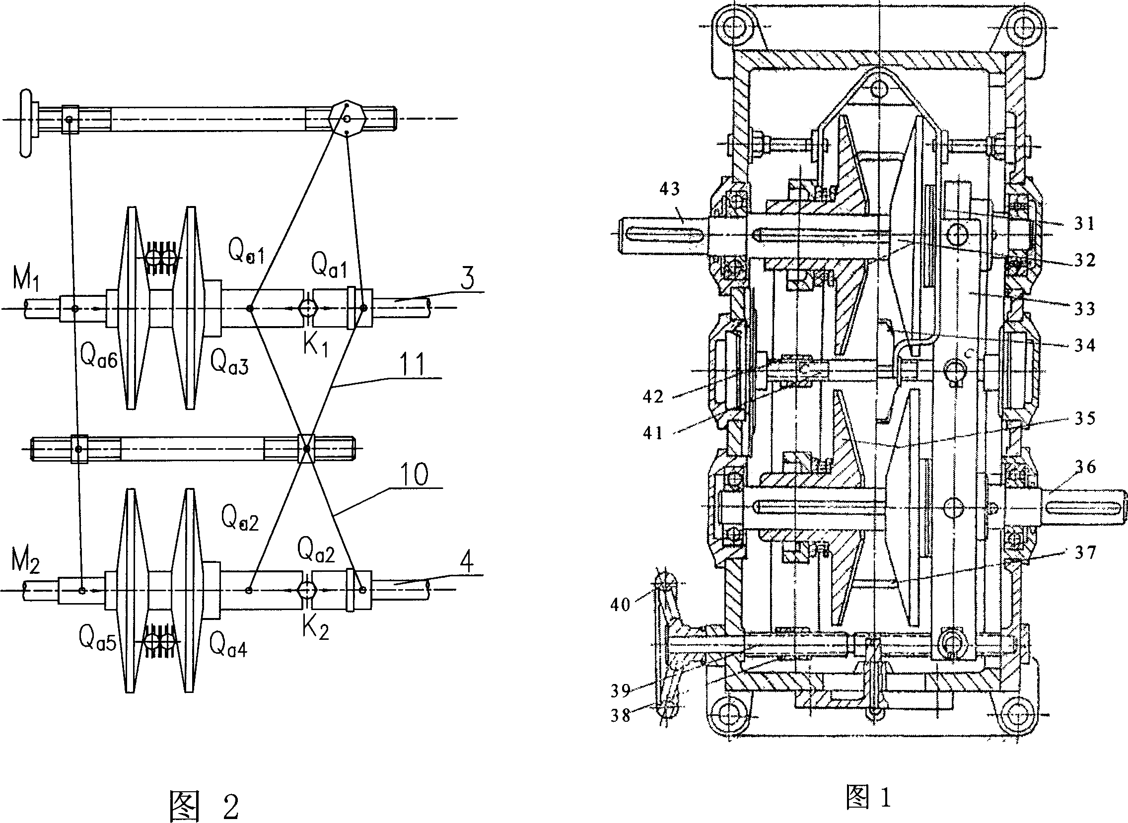
[0015] Referring to Fig. 3, Fig. 4 and Fig. 5, a roller-type continuously variable transmission with a scissor-shaped lever plate mainly includes two pairs of driving sprockets 2, 6, driven sprockets 1, 7, and Input shaft 3, output shaft 4, speed regulating lever, speed regulating screw mandrel 17, tensioning chain screw mandrel 19. The input shaft 3 and the output shaft 4 are installed in parallel, and a chain screw 19 is installed between the input shaft 3 and the output shaft 4, the driving sprocket 2, 6 is installed on the input shaft 3, and the driven sprocket 1, 7 is installed on the output shaft 4, a wedge-shaped clamping groove is formed between two relative sprocket surfaces 2,6 and 1,7, and a chain 18 is clamped as a transmission chain, and the transmission chain is a roller chain 18. One side of the input shaft 3 is equipped with a speed regulating screw mandrel 17 .

[0016] Speed ​​regulating lever comprises single lever 5 and long, short scissors shape lever pla...


PUM


Abstract

This invention relates to a chain stepless gear, in which, the input shaft and the output shaft are mounted parallel to a tensional chain screw mandrel, two opposite chain wheel faces form a wedge notch to clamp the chain as a drive chain characterizing that a speed lever is a single lever and long and short scissor-like lever plates, in which, the pivots of which are a same one mounted on the tensional chain screw mandrel and the speed screw mandrel, the active points of the lever plates are installed on two pressure rings, one is sleeved on the chain wheel handle, the other is covered on the pressure cam sleeved on the shaft, two V-shape notches are opened between the cam end face and the end face of the chain wheel handle filled with steel balls, the single lever takes the tensional screw mandrel as the pivot connected with the chain wheels mounted on the shafts, the right and left ends of the speed screw mandrel are screw rods connecting the single lever and the speed screw mandrel.

Description

(1) Technical field [0001] The invention relates to a continuously variable transmission, in particular to a chain type continuously variable transmission. (2) Background technology [0002] Chain-type continuously variable transmission can be divided into slide chain, roller chain, etc. according to its chain structure. A device that coordinates the speed of operation of multiple machines. The existing chain-type continuously variable transmission, such as the sliding plate chain-type continuously variable transmission, is a transmission mechanism with a flexible intermediate piece and a cone wheel, mainly including two pairs of driving and driven sprockets 35 that can move axially. , 32, input shaft 36, output shaft 43, speed control lever 33, speed control screw mandrel 39, Zhang chain screw mandrel 41, see Fig. 1. The input shaft and the output shaft are installed in parallel, and a chain screw is installed between the input and output shafts. The driving sprocket is i...

Claims


Application Information

Patent Timeline
Patent Type & Authority Applications(China)
IPC IPC(8): F16H9/24F16H7/08
Inventor 房诗建毛惠林
Owner 上海中纺机通用机械有限公司
Why Eureka
Try Eureka