

LED road-light light-source
A technology for LED street lamps and LED lamps, which is applied to light sources, electric light sources, point light sources, etc., can solve the problems of large size of LED street lamps, troublesome maintenance and operation methods, inconvenient installation and disassembly, etc., and achieves reasonable structural design, low cost, and installation. The effect of easy disassembly
Active Publication Date: 2007-03-28
SHENZHEN BANG BELL ELECTRONICS
View PDF0 Cites 32 Cited by
- Summary
- Abstract
- Description
- Claims
- Application Information
AI Technical Summary
Problems solved by technology
However, at present, the LED street lamps on the domestic and foreign markets all use the method of embedding LED lamps into the lamp housing to form an integrated lamp head, which is connected to the street lamp pole through bolts or screw lamps. This structure makes the LED street lamp larger in size and easy to install It is inconvenient to disassemble. If a certain LED lamp group in the street lamp is damaged, the entire lamp head needs to be disassembled, the lamp housing is opened, and a new LED lamp group is replaced. This kind of maintenance operation method is very troublesome.
In addition, the structural form of this lamp holder also makes its cost higher
Method used
View moreImage
Smart ImageViewing Examples

Examples
Embodiment 1
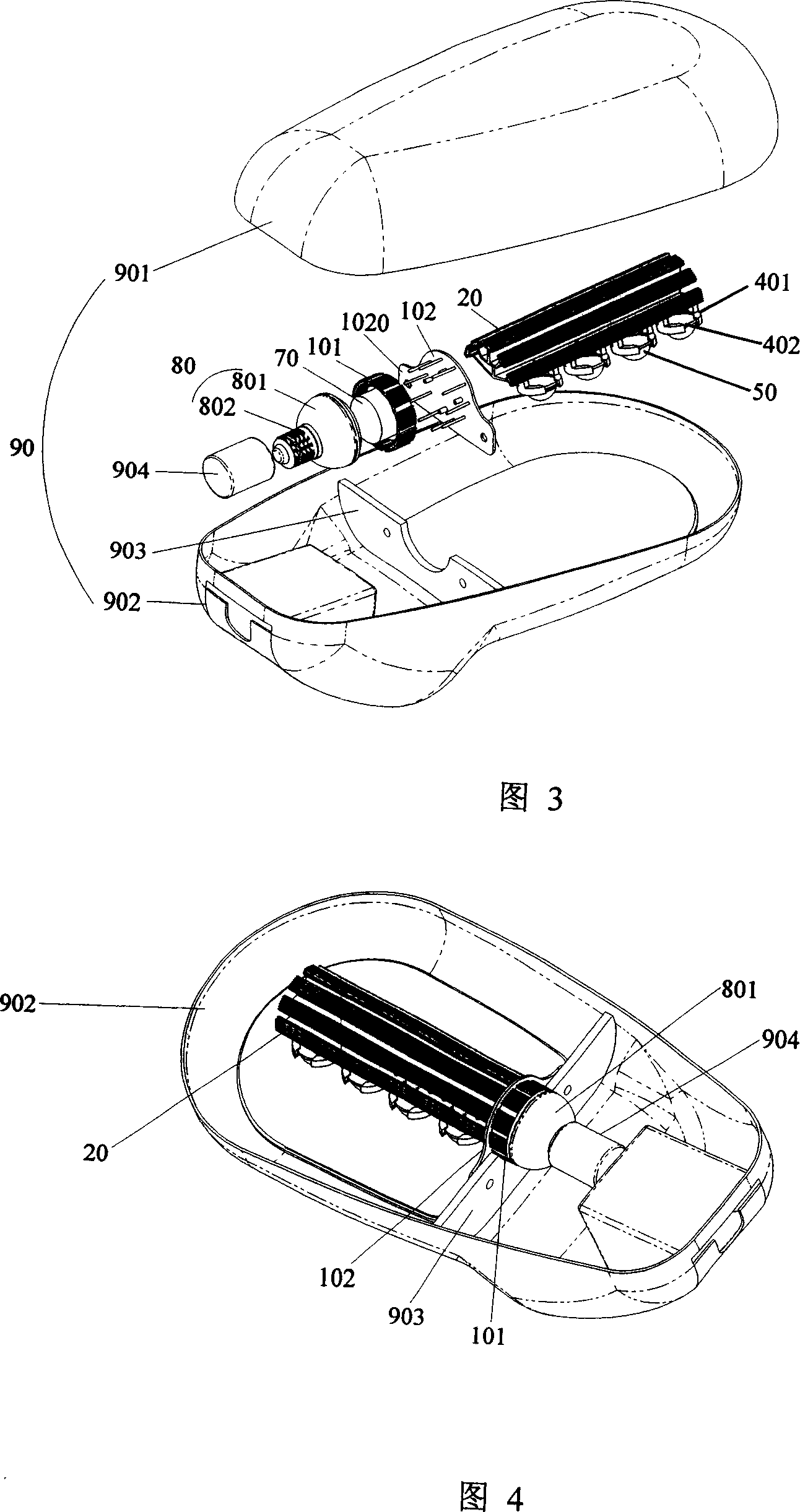
[0033] The first embodiment can also be installed in the lamp housing 90 correspondingly, which is the same as the second embodiment, only need to screw the threaded interface 802 into the ceramic lamp holder 904. Since the cover plate 102 has no extension part, there is no need to fix the cover plate 102, and there is no need to set a positioning plate 904 in the lamp housing 90. This design is a light source with low power, small size and light weight, and only the ceramic lamp holder 904 can support the weight of the entire light source.
Login to View More PUM
 Abstract
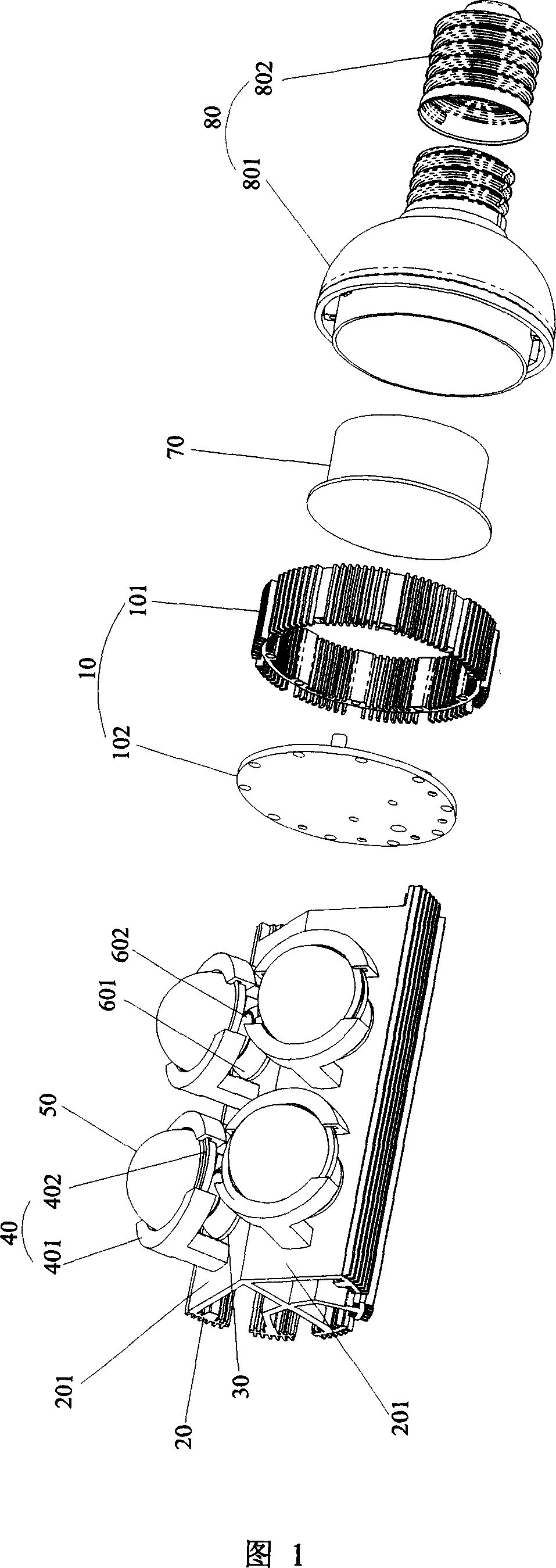
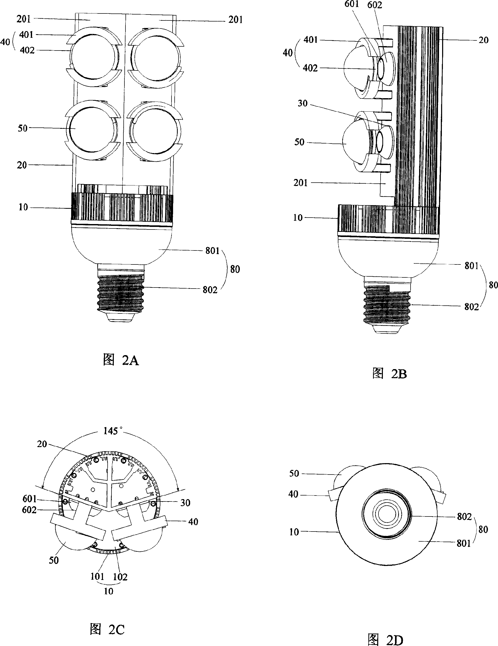
This invention relates to a light source of LED street lamps including a heat-radiation device and a light emitting device, in which, said radiation device includes a radiation base and a heat conduction base board set on the base, said light emitting device includes LED lamps set on the conducting base board, a supply connecting to the LED lamps, lenses covering the lamps and fixing frames of the lenses, the design of the light emitting device and the heat radiation device is reasonable, and the devices can be compatible with the lamp shells of high pressure Na and high pressure Hg street-lamps.
Description
technical field [0001] The invention relates to a street light source, in particular to an LED street light source. Background technique [0002] Most of the existing street light sources use high-pressure sodium lamps, high-pressure mercury lamps, etc., which consume a lot of power, and the working voltage needs to be raised to more than 1,000 volts. A transformer must be installed on the street lights to boost the voltage. Minutes or even ten minutes, the utilization rate of the power grid is low, which is a heavy burden on the power grid and a great waste of power resources. In order to overcome the above problems, a kind of LED street lamp has appeared, which has the advantages of energy saving, environmental protection, long service life and no need for transformer to start. However, at present, the LED street lamps on the domestic and foreign markets all use the method of embedding LED lamps into the lamp housing to form an integrated lamp head, which is connected to ...
Claims
Login to View More Application Information
Patent Timeline
 IPC IPC(8): F21S8/00F21V29/00F21V19/00F21W131/103F21Y101/02F21V29/50F21Y115/10
CPCF21S8/086F21K9/13F21Y2101/02F21W2131/103Y02B20/72F21K9/23F21Y2115/10
Inventor李盛远
OwnerSHENZHEN BANG BELL ELECTRONICS