Electrical connector having ground planes

A technology for electrical connectors and grounding plates, which is applied in the direction of connection, two-part connection device, and parts of the connection device. Smooth insertion and removal, full contact effect

Inactive Publication Date: 2007-03-28
HIROSE ELECTRIC GROUP
View PDF1 Cites 3 Cited by
  • Summary
  • Abstract
  • Description
  • Claims
  • Application Information

AI Technical Summary

Problems solved by technology

This means that an elastic piece is required to obtain elastic displacement for the width of the slit, which will not only increase the elastic force, but also fail to ensure sufficient elastic displacement when the slit width is small, making each slit The size of the gap is uneven, resulting in poor contact at other slit positions
[0005] Since there are many such slits in the entire connector, the insertion and extraction force of the connector increases, and as a result, there is a tendency to twist the insertion and extraction, which will adversely affect the connector.

Method used


Image

  • Electrical connector having ground planes
  • Electrical connector having ground planes
  • Electrical connector having ground planes

Examples


Embodiment Construction

[0027] Embodiments of the present invention will be described below with reference to FIGS. 1 to 5 of the drawings.

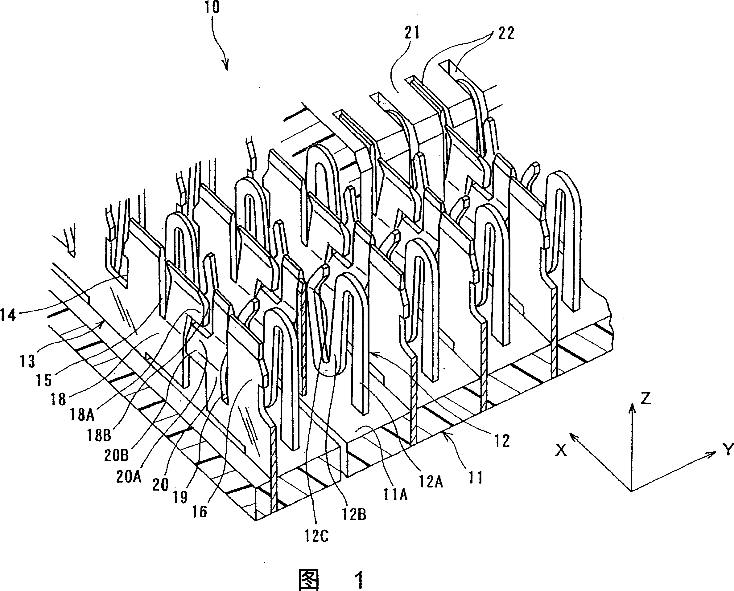
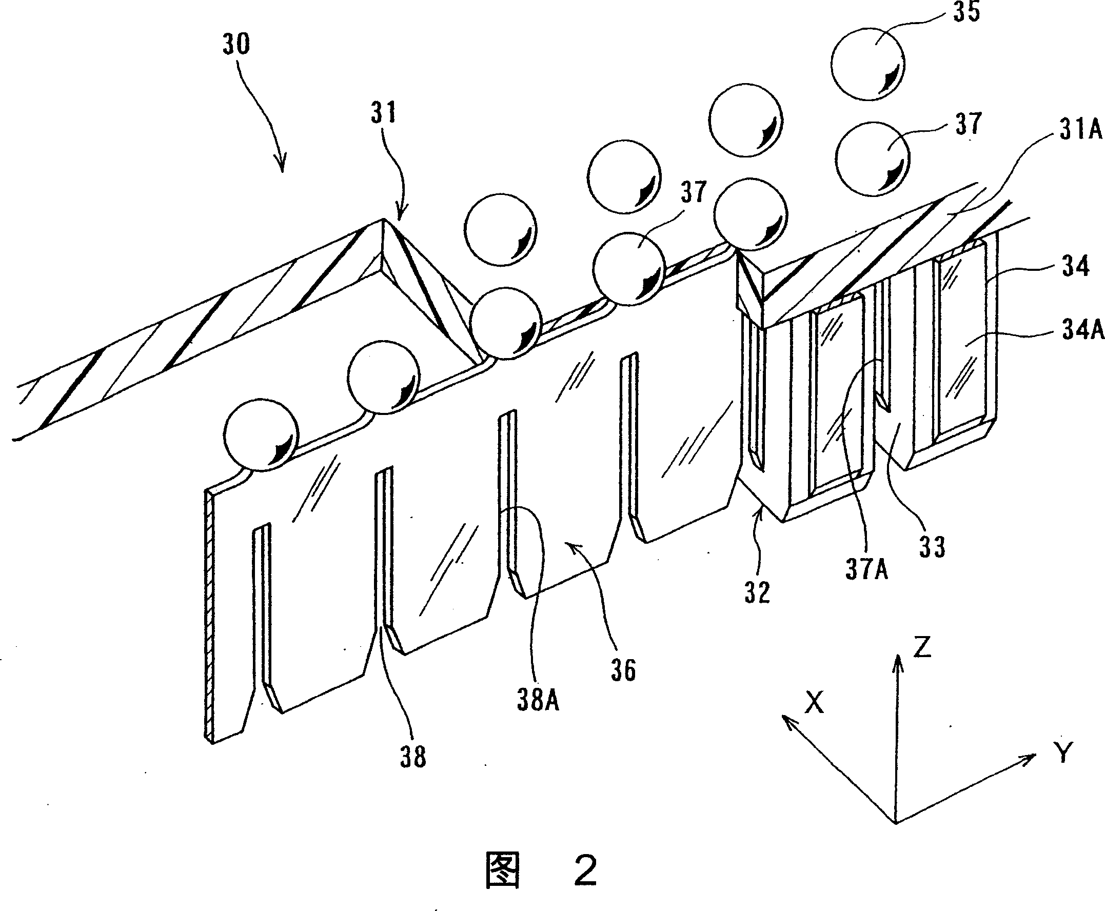
[0028] FIG. 1 shows the connector of the present embodiment, and FIG. 2 shows a mating connector which is fitted and connected to the connector. Both figures are perspective views showing the part of the fitted connection.

[0029] In the connector 10 of the present embodiment shown in FIG. 1 , the signal terminals 12 and the ground plate 13 are supported by a housing 11 made of an electrically insulating material. In the figure, the signal terminals 12 and the ground plates 13 have surfaces substantially parallel to the XZ plane of the three-dimensional space coordinates XYZ, and are alternately arranged at regular intervals in the Y direction.

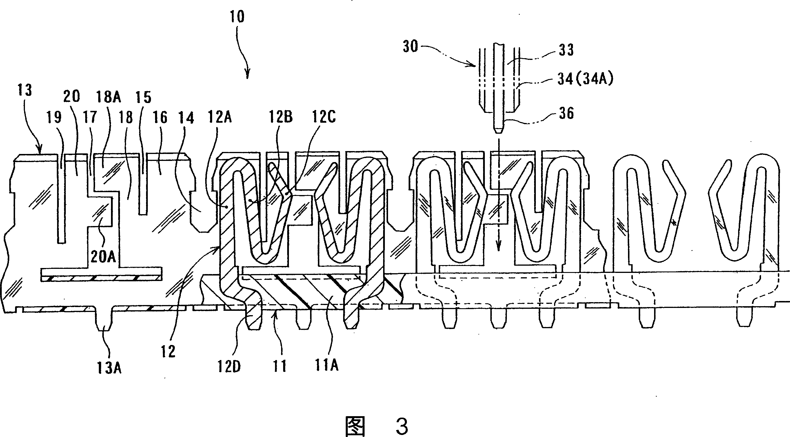
[0030] As shown in FIGS. 1 and 3 , a plurality of signal terminals 12 located on one XZ plane are formed by applying contour processing to the surface of a metal plate while maintaining a flat surface, and the plate s...


PUM


Abstract

An electrical connector has ground planes. Each ground plane (13) crosses counter ground planes (36) of the counter connector (30) so as to make a lattice structure when the counter connector (30) is fitted to the connector. The contact section (12C) of a signal terminal (12) of the connector has a plane surface perpendicular to the surface of the corresponding counter contact section (34A) of the counter signal terminal (34), and formed at a flexible elastic arm (12B) in the plane surface. The ground plane (13) has pressure-welding sections (18B) and (20B), which individually elastically contact with the facing inner surfaces of each slit, at a portion to be put into each slit of the counter ground plane (36).

Description

technical field [0001] The present invention relates to electrical connectors with attached ground plates. Background technique [0002] As such a connector, for example, a connector disclosed in Patent Document 1 is known. In this patent document 1, two connectors to be fitted and connected each have a plurality of ground plates intersecting to form a grid, and the contact portions of the signal terminals are located in each grid-like area. The plurality of ground plates of one connector are respectively formed with slits opening in the fitting direction at predetermined pitches, and the ground plates of the other connector disposed in a direction perpendicular to the ground plates enter the slits. On the ground plate of the other connector, an elastic piece is formed by cutting a groove, and the elastic piece enters into the slit and comes into elastic contact with the inner surface of the slit. In this way, the ground plates of the two connectors form a grid pattern and...

Claims


Application Information

Patent Timeline
Patent Type & Authority Applications(China)
IPC IPC(8): H01R13/648H01R13/652H01R13/11
CPCH01R23/688H01R13/65802H01R13/65807H01R13/6585
Inventor 松尾勉大志田直
Owner HIROSE ELECTRIC GROUP
Why Eureka
Try Eureka