Check patentability & draft patents in minutes with Patsnap Eureka AI!

Electronic device and its pivot mechanism

A technology for electronic devices and pivots, applied in pivots, hinge/pivot support structures, rack/frame structures, etc., can solve problems such as increasing product defect rates, affecting the overall performance of electronic devices, and interfering with radio frequency signals.

Active Publication Date: 2007-03-28
ASUSTEK COMPUTER INC
View PDF0 Cites 0 Cited by
  • Summary
  • Abstract
  • Description
  • Claims
  • Application Information

AI Technical Summary

Problems solved by technology

In the pivot mechanism, the metal material itself will interfere with the radio frequency signal, thereby affecting the overall performance of the electronic device (Performance)
In addition, because the overall structure is relatively complex, the defect rate of the product increases

Method used


Image

  • Electronic device and its pivot mechanism
  • Electronic device and its pivot mechanism
  • Electronic device and its pivot mechanism

Examples


Embodiment Construction

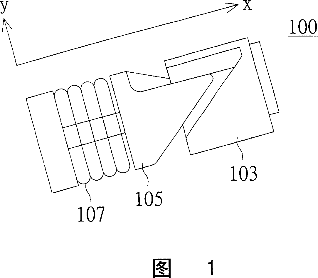
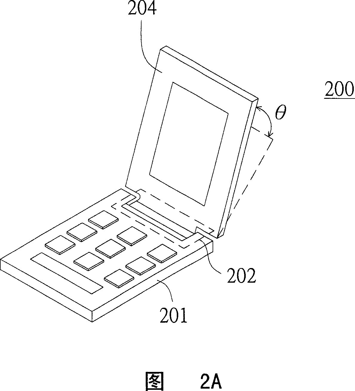
[0014] Please refer to FIG. 2A , which is a perspective view of the electronic device. The electronic device is, for example, a mobile phone. As shown in FIG. 2A , the electronic device 200 includes a body 201 and a pivot mechanism 202 . Through the configuration of the pivot mechanism 202 , the casing 204 of the electronic device 200 can be driven to rotate relative to the electronic device 200 . The pivot mechanism 202 includes a fixing part 203 and a rotating part 205 (as shown in FIG. 2E ). Through the following embodiments, the angle of rotation of the rotating member and the stroke of its movement can be fixed to replace the previous pivot mechanism (as shown in Figure 1) composed of rotating members, fixing members and springs, and the pivot can be Mechanisms are used in various electronic devices.

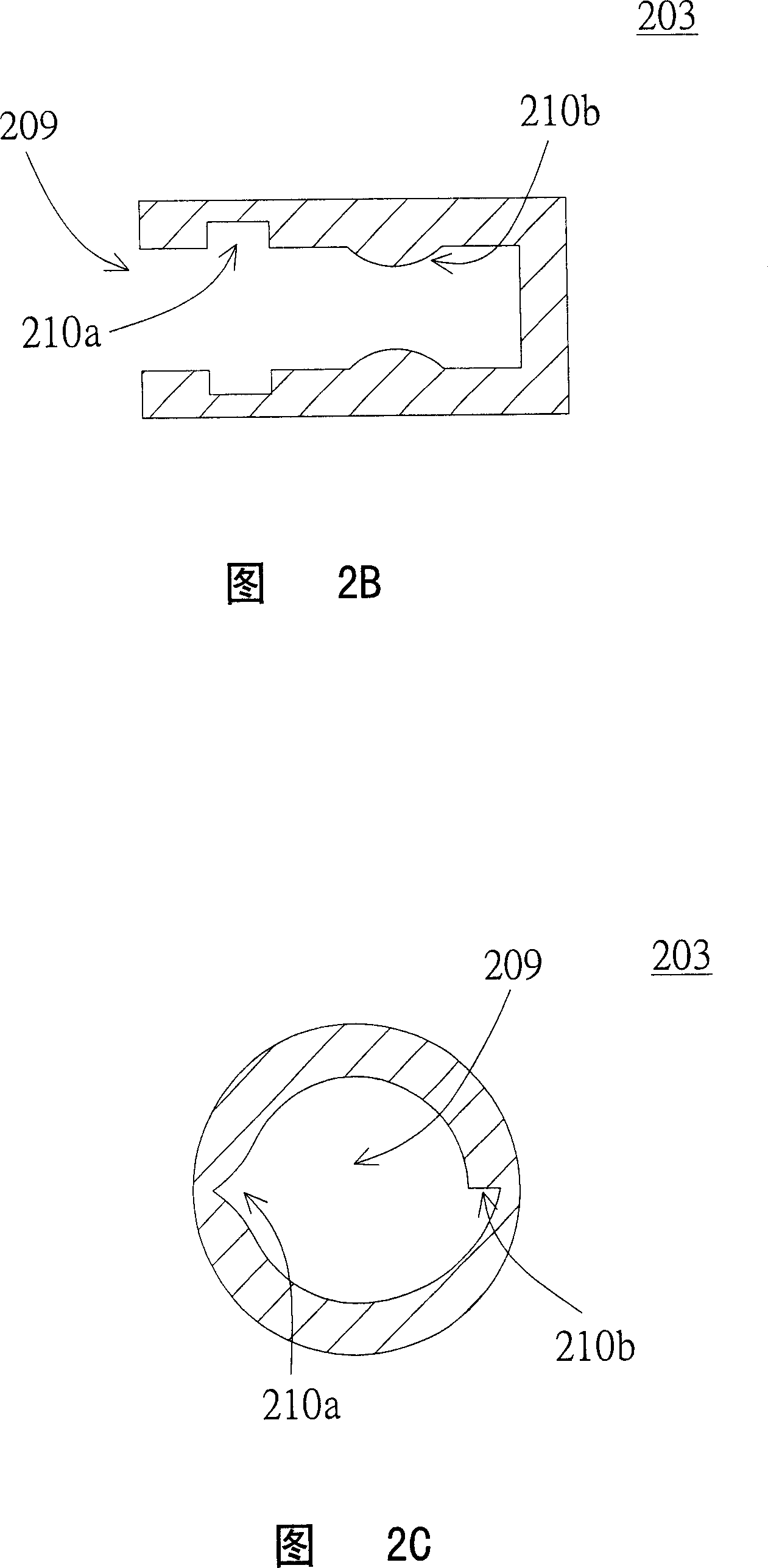
[0015] Please refer to FIG. 2B and FIG. 2C at the same time. FIG. 2B is a cross-sectional view of the fixing member, and FIG. 2C is a schematic cross-sectional view of t...


PUM


Abstract

The invention relates to pivotal institutions, which is located in an electronic device noumenon. This pivotal institution includes a fixing part and a rotating part. The fixing part is fixed in the noumenon and it has a socket, the socket surface is a melody surface. The rotating part is embedded in the slot to make interference. When rotate these rotating parts, the melody surface of fixing part interferes and has an extrusion to the rotating part, which can make the rotating parts to produce a translation.

Description

technical field [0001] The present invention relates to a pivot mechanism, and more particularly to a pivot mechanism applied in an electronic device. Background technique [0002] Please refer to FIG. 1 , which is a perspective view of a pivot mechanism in a conventional electronic device. In an electronic device, such as a flip cover of a mobile phone, the pivot mechanism 100 of the flip cover includes: a fixing part 103 , a rotating part 105 and a spring 107 . The rotating member 105 rotates around the fixing member 103 . When the rotary member 105 is rotated in the Y direction, a stroke in the X direction will also be generated simultaneously. Therefore, by configuring the spring 107, the rotating member 105 can be automatically returned to the equilibrium position. Through the rotation or translation in the X direction, the Y direction and the direction, the flip cover can also be rotated or moved. [0003] However, the current fixing part 103, the rotating part 105...

Claims


Application Information

Patent Timeline
Patent Type & Authority Applications(China)
IPC IPC(8): H05K7/16H05K7/18F16C11/00
Inventor 张木财
Owner ASUSTEK COMPUTER INC
Features
  • R&D
  • Intellectual Property
  • Life Sciences
  • Materials
  • Tech Scout
  • Unparalleled Data Quality
  • Higher Quality Content
  • 60% Fewer Hallucinations
Learn More