Observing device and fluorescent light observing device

An observation device and fluorescence technology, applied in optics, optical components, instruments, etc., can solve problems such as too small numerical aperture, difficult lighting, difficult zooming, etc., and achieve the effect of ensuring space

Inactive Publication Date: 2007-03-28
OLYMPUS CORP
View PDF3 Cites 21 Cited by
  • Summary
  • Abstract
  • Description
  • Claims
  • Application Information

AI Technical Summary

Problems solved by technology

[0006] However, since conventional microscope observation devices change the observation magnification by changing the magnification of the telephoto zoom relay lens, it is difficult to change the magnification within a wide range of magnifications.
That is, since the same objective lens and imaging lens are used from a smaller magnification to a larger magnification, there is an inconvenience that the numerical aperture is too small and the resolution decreases at a smaller magnification
[0007] In addition, in

Method used


Image

  • Observing device and fluorescent light observing device
  • Observing device and fluorescent light observing device
  • Observing device and fluorescent light observing device

Examples


no. 1 Embodiment approach

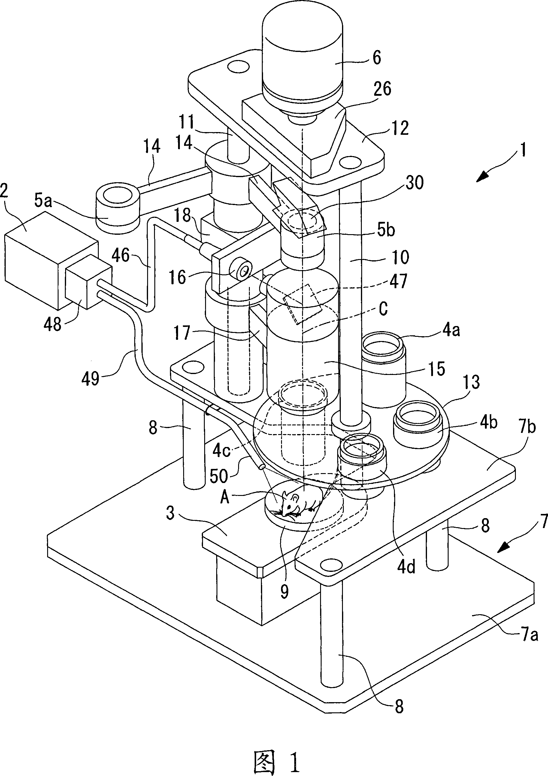
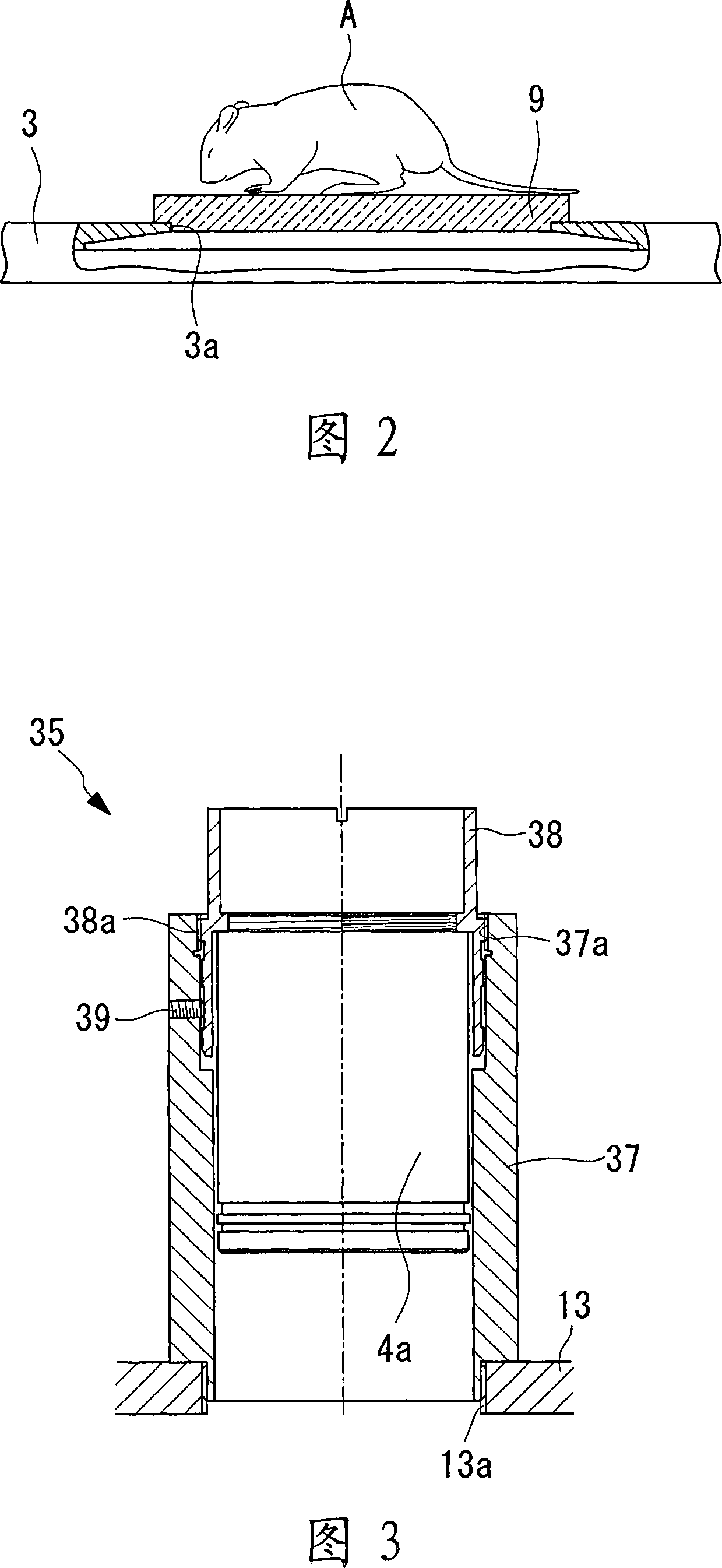
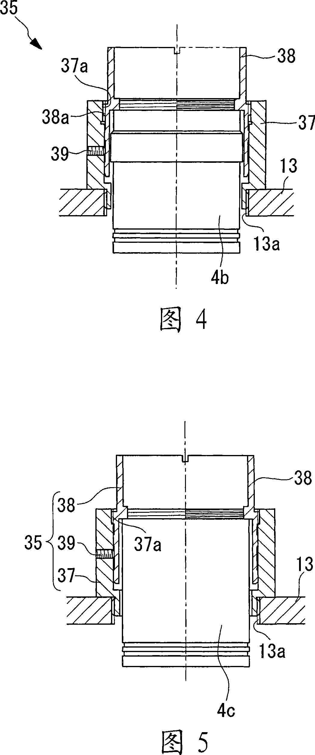
[0106] Hereinafter, a microscope observation device according to a first embodiment of the present invention will be described with reference to FIGS. 1 to 15 .

[0107] As shown in FIG. 1 , the microscope observation device 1 according to the present embodiment has: a light source 2 for generating light irradiated on experimental small animals such as mice or other samples A; a stage 3 on which the sample A is placed; The objective lens unit 4a~4d of the return light amplification of the object lens unit 4a~4d; The imaging lens unit 5a, 5b that makes the image on the sample A enlarged by the objective lens unit 4a~4d magnify, imaging; The image camera (camera unit)6.

[0108] The stage 3 is arranged on a base 7 arranged horizontally. The base 7 has: the 1st base 7a provided on the horizontal installation surface; and the 2nd base 7b horizontally arrange|positioned at intervals above the 1st base 7a. Between the 1st base 7a and the 2nd base 7b, the some spacer member 8 which...

no. 2 Embodiment approach

[0158] Next, a microscope observation device 60 according to a second embodiment of the present invention will be described with reference to FIG. 16 . In the description of the present embodiment, the same reference numerals are attached to the parts having the same configuration as those of the microscope observation apparatus 1 according to the first embodiment described above, and the description thereof will be omitted.

[0159] As shown in FIG. 16 , the microscope observation device 60 according to this embodiment differs from the microscope observation device 1 according to the first embodiment in that the turntable 13 , the arm 17 and the second turntable 62 are rotatably attached to a single column 61 . .

[0160] That is, as shown in FIG. 16 , the microscope observation device 60 according to this embodiment is equipped with a base 7 for fixing the stage 3 on which the sample A is mounted, and a support 61 extending vertically from the base 7 . A turntable 13 and a ...

no. 3 Embodiment approach

[0164] Next, a microscope observation device 70 according to a third embodiment of the present invention will be described below with reference to FIG. 17 .

[0165] In the description of the present embodiment, the same reference numerals are attached to the parts having the same configuration as those of the microscope observation apparatuses 1 and 60 according to the above-mentioned embodiments, and their descriptions are omitted.

[0166] The microscope observation device 70 according to the present embodiment is the same as the microscope observation device 60 according to the second embodiment in that it has a single support 61 fixed to the base 7 .

[0167] As shown in FIG. 17 , the microscope observation device 70 according to this embodiment has: a first lens group 71 composed of a low-power objective lens unit 4a and an imaging lens unit 5a; a high-power objective lens unit 4d, a zoom device 15, and an imaging lens unit 5a; The second lens group 72 formed by combinin...


PUM


Abstract

An image can be captured with a high resolution to improve an observing accuracy without excessively reducing a numeric aperture despite a smaller magnification. A microscope observing device comprising a light source for applying an exciting light or a lighting light to a specimen placed on a stage, an object lens disposed oppositely on the stage to magnify a fluorescent light or a reflection light from the specimen, an imaging lens for forming an image on the specimen magnified by the object lens, and an imaging means for picking up the image on the specimen formed by the imaging lens, wherein a mechanism for switching object lenses is provided along with a plurality of object lenses with different magnifications, and a mechanism for switching imaging lenses (5a, 5b) is provided along with a plurality of imaging lenses with different magnifications.

Description

technical field [0001] The present invention relates to an observation device such as a microscope observation device and a fluorescence observation device for observing living bodies, organs, tissues, and the like. Background technique [0002] Conventionally, a microscope observation device disclosed in Patent Document 1 has been known as a microscope observation device. The microscope observation device has: an objective lens arranged opposite to the sample; an imaging lens for imaging a magnified image in an imaging unit such as a CCD camera; A zoom relay lens that continuously changes the magnification inside. [0003] According to this microscope observation device, the objective lens and the imaging lens are fixed, and even if the telephoto zoom relay lens is inserted and removed between them, the parfocal position of the imaging surface does not change, and the deterioration of the image due to zooming is small, and the Improve operability or performance. [0004]...

Claims


Application Information

Patent Timeline
IPC IPC(8): G02B21/00
Inventor 河野芳弘清水敬之祐川实望月刚本田进林一博
Owner OLYMPUS CORP
Why Eureka
Try Eureka