Bearing assembly

A technology of bearing components and bearings, applied in the direction of bearings, shafts and bearings, shafts, etc., can solve problems such as uneven passage, bearing wear, etc., and achieve the effect of simplifying assembly and increasing service life

Inactive Publication Date: 2007-04-04
汉斯·沙赫勒克尔
View PDF0 Cites 5 Cited by
  • Summary
  • Abstract
  • Description
  • Claims
  • Application Information

AI Technical Summary

Problems solved by technology

It is often the case that the grease acquires an uneven path close to the two bearings through the annular gap between the spindle and the intermediate piece, causing premature wear of the bearings

Method used


Image

  • Bearing assembly
  • Bearing assembly
  • Bearing assembly

Examples


Embodiment Construction

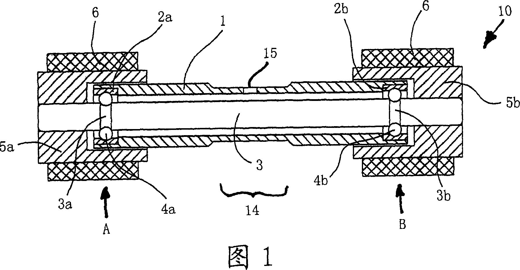
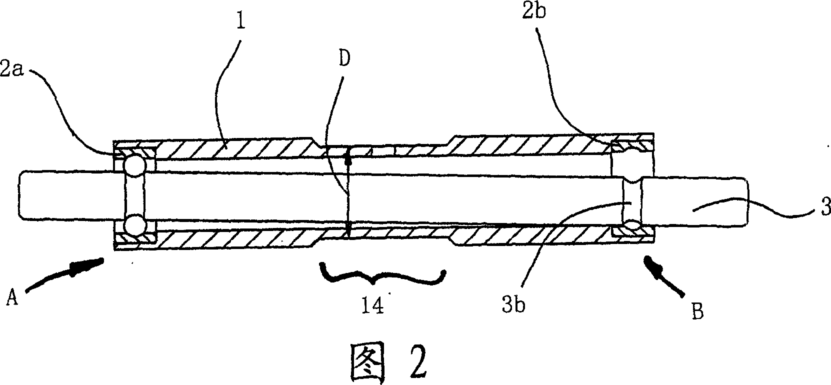
[0021] Referring now to Figures 1 and 2, there is shown a bearing assembly for a fixed roll 10 known from the prior art, Figure 1 shows a bearing assembly with a fixed intermediate piece 1 comprising a bearing outer ring 2a and 2b, bearing outer rings 2a and 2b are arranged in the ends of this intermediate piece 1 in grooves machined in the inner circumference of the intermediate piece 1 . Spindle grooves 3a and 3b are machined in the spindle 3, which form the inner rings of the bearings A and B which house the ball rows 4a and 4b and the cage. The roll bodies 5a and 5b to which the roll mantle 6 is mounted are pressed in place on the ends of the mandrel 3 protruding beyond the bearings A and B. Lubricating holes 15 are drilled in the middle of the intermediate part 1 in the region of the saddle 14 , through which the bearings A and B are lubricated.

[0022] Referring now to Figure 2, in an assembly stage prior to the state shown in Figure 1 with respect to a bearing assembl...


PUM


Abstract

The invention provides a bearing assembly for fixed rollers (210, 310) particularly for a drawing unit of spinning machine. The bearing assembly comprises a shell-like middleware (21, 31) for installing a first bearings (2A, 3A) and a second bearing (2B, 3B). The first bearing (2A, 3A) and second bearing (2B, 3B) is used for the mandrel (23, 33) of the fixed rollers (210, 310). The bearing assembly is characterized in that the outer rings (22a, 22b, 32a, 32b) of the first bearing (2A, 3A) and the second bearing (2B, 3B) are mounted on the outer periphery of the middleware.

Description

technical field [0001] The invention relates to a bearing assembly for a fixed roll, in particular for a drafting unit of a spinning machine, comprising a middle-piece of shell type mounting a first bearing and a second bearing, The first bearing and the second bearing are used to mount a mandrel for the fixed roller. Background technique [0002] In known bearing assemblies for stationary rolls, such as pressure rolls for drafting units of spinning machines, axially assembled stationary rolls configured with a cylindrical shell fitted with a roll mantle are mounted against On a spindle passing through a so-called intermediate piece, the spindle is mounted rotatably via rolling contact bearings arranged in the intermediate piece. [0003] The saddle-shaped part provided in the middle of the intermediate part for fixedly fastening the intermediate part to the drafting unit has a defined width and a predetermined outer diameter of 9.5 mm for mounting the fixed roll on a globa...

Claims


Application Information

Patent Timeline
Patent Type & Authority Applications(China)
IPC IPC(8): D01H5/70
CPCD01H5/74F16C13/02F16C2340/18
Inventor 汉斯·沙赫勒克尔
Owner 汉斯·沙赫勒克尔
Why Eureka
Try Eureka