Guide valve type electromagnetic valve

A solenoid valve and pilot valve technology, applied in the direction of lift valve, valve details, valve device, etc., can solve the problems of increasing the number of parts, man-hours and costs, being adsorbed on the blocking surface, and unable to be separated, etc., to achieve low cost, The effect of reducing costs

Inactive Publication Date: 2007-04-04
FUJIKOKI MFG CO LTD
View PDF1 Cites 11 Cited by
  • Summary
  • Abstract
  • Description
  • Claims
  • Application Information

AI Technical Summary

Problems solved by technology

[0011] However, in the above-mentioned existing pilot valve type solenoid valve, since the entire upper end surface (annular flat surface) of the main valve element is in surface contact with the blocking surface (annular flat surface), the The surface tension of the fluid (refrigerant) and lubricating oil on the surface (suction cup effect), sometimes even if the pilot valve core 35 wants to return to the valve c

Method used


Image

  • Guide valve type electromagnetic valve
  • Guide valve type electromagnetic valve
  • Guide valve type electromagnetic valve

Examples


Embodiment Construction

[0027] Hereinafter, embodiments of the pilot type solenoid valve of the present invention will be described with reference to the drawings.

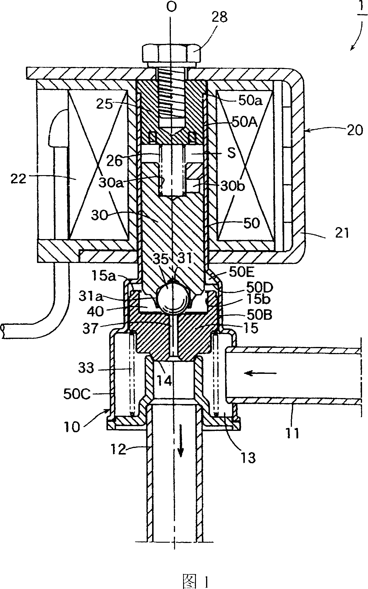
[0028] Fig. 1 is a longitudinal sectional view showing an embodiment of a pilot type solenoid valve of the present invention.

[0029] In the pilot solenoid valve 1 of the illustrated embodiment, the parts having the same structure or function as those of the pilot solenoid valve 1' of the conventional example shown in FIG. 4 above are given the same reference numerals. Repeated explanations are omitted, and the differences are highlighted below.

[0030] The pilot solenoid valve 1 of this embodiment is also used in refrigeration cycles such as air conditioners, and is different from the above-mentioned conventional example in the structure of the pilot pipe.

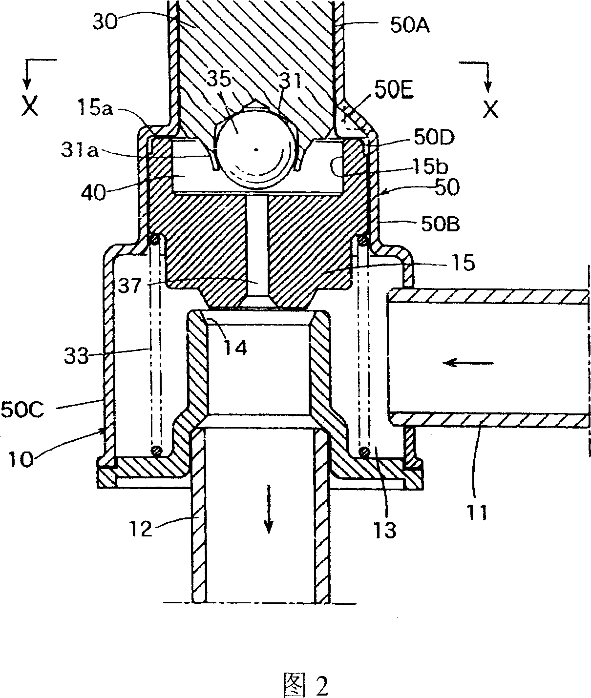
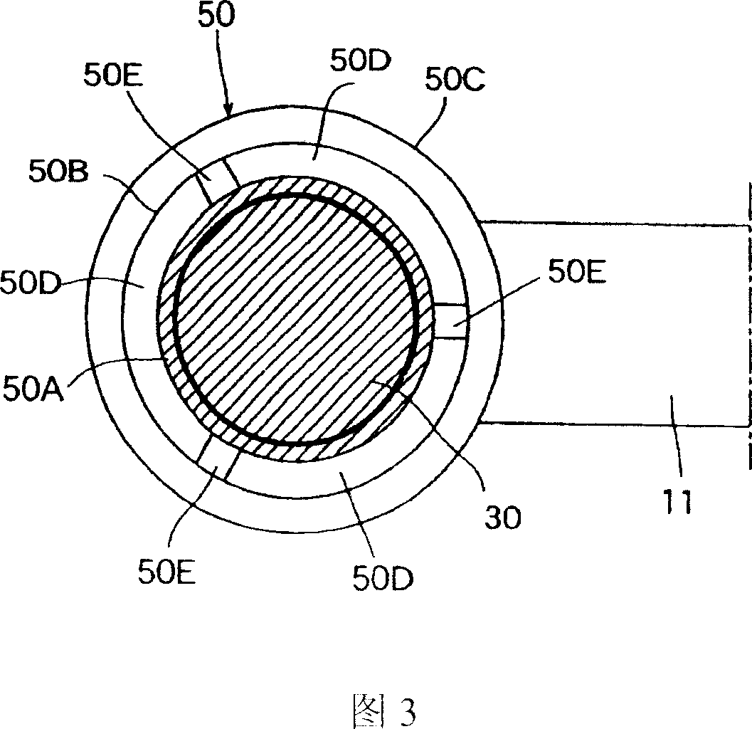
[0031] That is, as shown in FIGS. 2 and 3 , the guide pipe 50 of this embodiment includes: a small-diameter portion 50A slidably inserted into the plunger 30 ; a large-diameter p...


PUM


Abstract

The present invention provides a pilot type solenoid valve capable of preventing the main valve element from not returning certainly without bringing about increase in the number of component parts, man-hours, or the cost. The pilot type solenoid valve 1 of the present invention executes opening and closing driving of the pilot valve core 35 by an electromagnetic actuator 20. A main valve element15 opening and closing complies with the motions of the pilot valve core 35. The pilot type solenoid valve 1 has a stopper preventing the main valve core 15 from moving in the opening direction, wherein the stopper is composed of a stopper surface part 50D where the end face of the main valve core 15 runs against and a recessed part 50E recessing from the stopper surface part 50D to the opening direction of the main valve core.

Description

technical field [0001] The present invention relates to a pilot valve type (Pylot type) electromagnetic valve, which is guided by an electromagnetic actuator composed of a coil for energizing and exciting, an attractor arranged on the inner peripheral side of the coil, and a plunger arranged opposite to the attractor. The spool is driven to open and close, and the main spool is opened and closed along with the pilot spool. Background technique [0002] FIG. 4 shows an example of a conventional pilot valve type solenoid valve of this type (see also Patent Document 1 and the like below). The pilot valve solenoid valve 1' of the illustrated example is used in refrigeration cycles such as air conditioners, and includes: a valve body 10, which is provided with a main valve chamber 13 having a main valve seat (valve port) 14; The inlet joint (flow port) 11 connected to the main valve chamber 13 and the outlet joint (flow port) 12 connected downstre...

Claims


Application Information

Patent Timeline
IPC IPC(8): F16K1/00F16K31/06
CPCF16K1/52F16K27/029F16K31/0651F16K31/34
Inventor 铃木健一小柳津薰
Owner FUJIKOKI MFG CO LTD
Why Eureka
Try Eureka