Detachable balancing optical assembly

A detachable technology for optical components, which is applied in the field of detachable balanced optical components, can solve problems such as unbalance, easy loosening of weight 133, and overall rotation away from the optical component 1, so as to improve the good rate, save costs, increase The effect of reliability

Inactive Publication Date: 2007-04-04
PRODISC TECH INC
View PDF0 Cites 3 Cited by
  • Summary
  • Abstract
  • Description
  • Claims
  • Application Information

AI Technical Summary

Problems solved by technology

[0008] However, when the optical assembly 1 runs at a high speed for a long time, the weight 133 is likely to loosen or even break awa

Method used


Image

  • Detachable balancing optical assembly
  • Detachable balancing optical assembly
  • Detachable balancing optical assembly

Examples


Embodiment Construction

[0038] A detachable balanced optical assembly according to a preferred embodiment of the present invention will be described below with reference to related drawings.

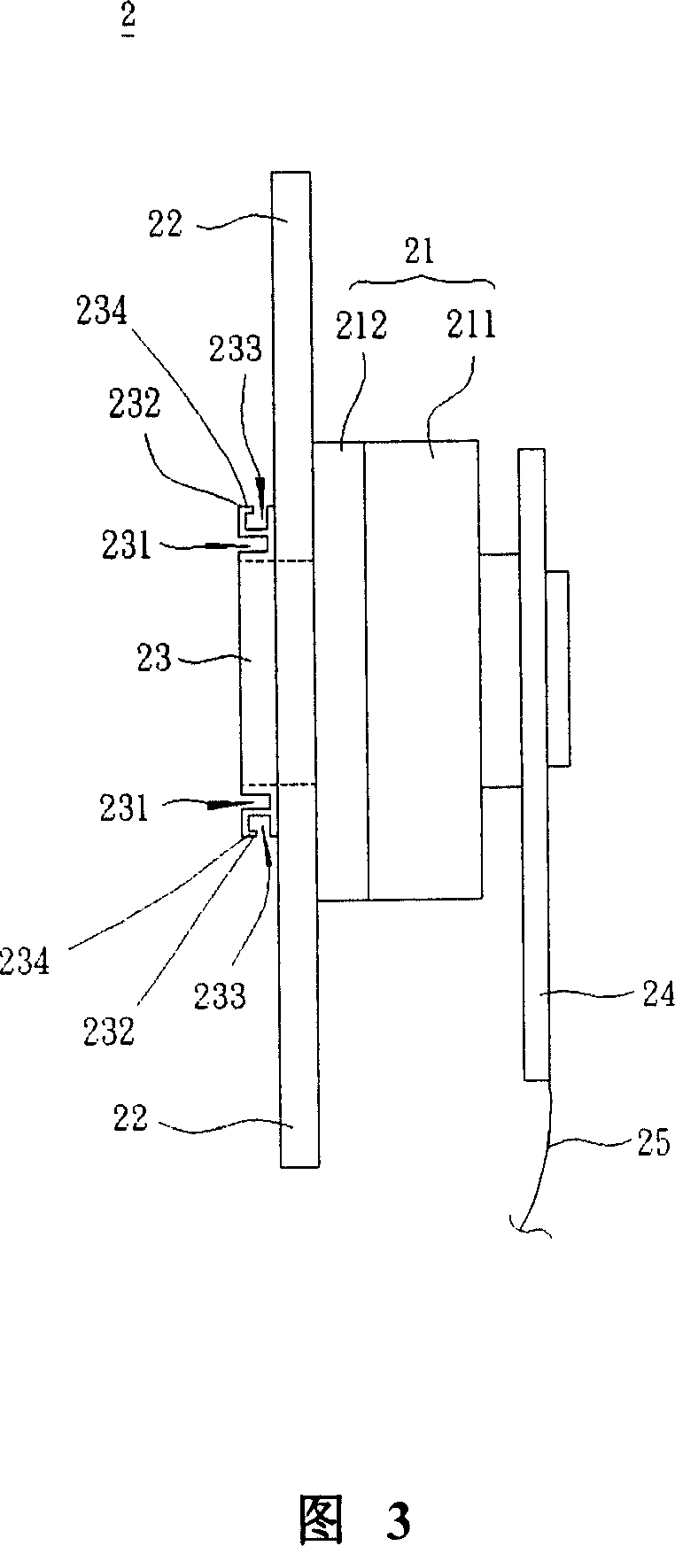
[0039] As shown in FIG. 3 , the detachable balanced optical assembly 2 according to a preferred embodiment of the present invention includes a motor 21 , a color wheel 22 and a cover 23 .

[0040] The motor 21 is arranged on one side of the color wheel 22. In this embodiment, the motor 21 is composed of a motor body 211 and an axis cover 212, and the axis cover 212 is a hole fitted in the center of the color wheel 22. And it is connected with the motor body 211 . Here, the motor body 211 is mainly composed of a magnet coil (not shown in the figure), a silicon steel sheet (not shown in the figure) and a coil (not shown in the figure). When the coil is energized, the steel sheet generates a magnetic force and a magnetic field, and the magnetic field changes in an orderly manner through the positive and negative ...


PUM


Abstract

A balanced optical component of detachable type is prepared as setting motor at one side of color wheel and coverage plate at another side of color wheel, setting a force exerting region on one surface of coverage plate as said surface being set opposite to color wheel.

Description

technical field [0001] The invention relates to a balanced optical assembly, in particular to a detachable balanced optical assembly. Background technique [0002] Image projection system is one of the most popular sub-items in the current photoelectric industry, and the digital light processing (Digital Light Processing, DLP) projector in the current popular projection system adopts digital control and uses the principle of reflected light After the light source is collected, it is focused through the lens and then passes through the color filter of the red, blue and green three-color filter, and is projected onto the digital micro-mirror device (Digital Micro-mirror Device, DMD). Since the digital micro-mirror device has many The tiny movable mirror controls the tilt angle and deflection time of the movable mirror through the driving electrodes, and then switches the reflection direction of the light to be projected by the lens to form an image. [0003] As shown in FIG. ...

Claims


Application Information

Patent Timeline
IPC IPC(8): G03G21/14G02B7/00G02B27/18
Inventor 王志煌张光华金克恕
Owner PRODISC TECH INC
Why Eureka
Try Eureka