High dehydration type rotation pressurization dehydrator

A dehydrator and rotating shaft technology, applied in the direction of presses, filtration separation, separation methods, etc., can solve the problems of insufficient dehydration and inability to form a uniform liquid content.

Inactive Publication Date: 2007-04-04
TOMOE ENGINEERING CO LTD
View PDF1 Cites 2 Cited by
  • Summary
  • Abstract
  • Description
  • Claims
  • Application Information

AI Technical Summary

Problems solved by technology

[0009] That is, in the deliquified cake discharged outside the machine, there are parts where the

Method used


Image

  • High dehydration type rotation pressurization dehydrator
  • High dehydration type rotation pressurization dehydrator
  • High dehydration type rotation pressurization dehydrator

Examples


Embodiment Construction

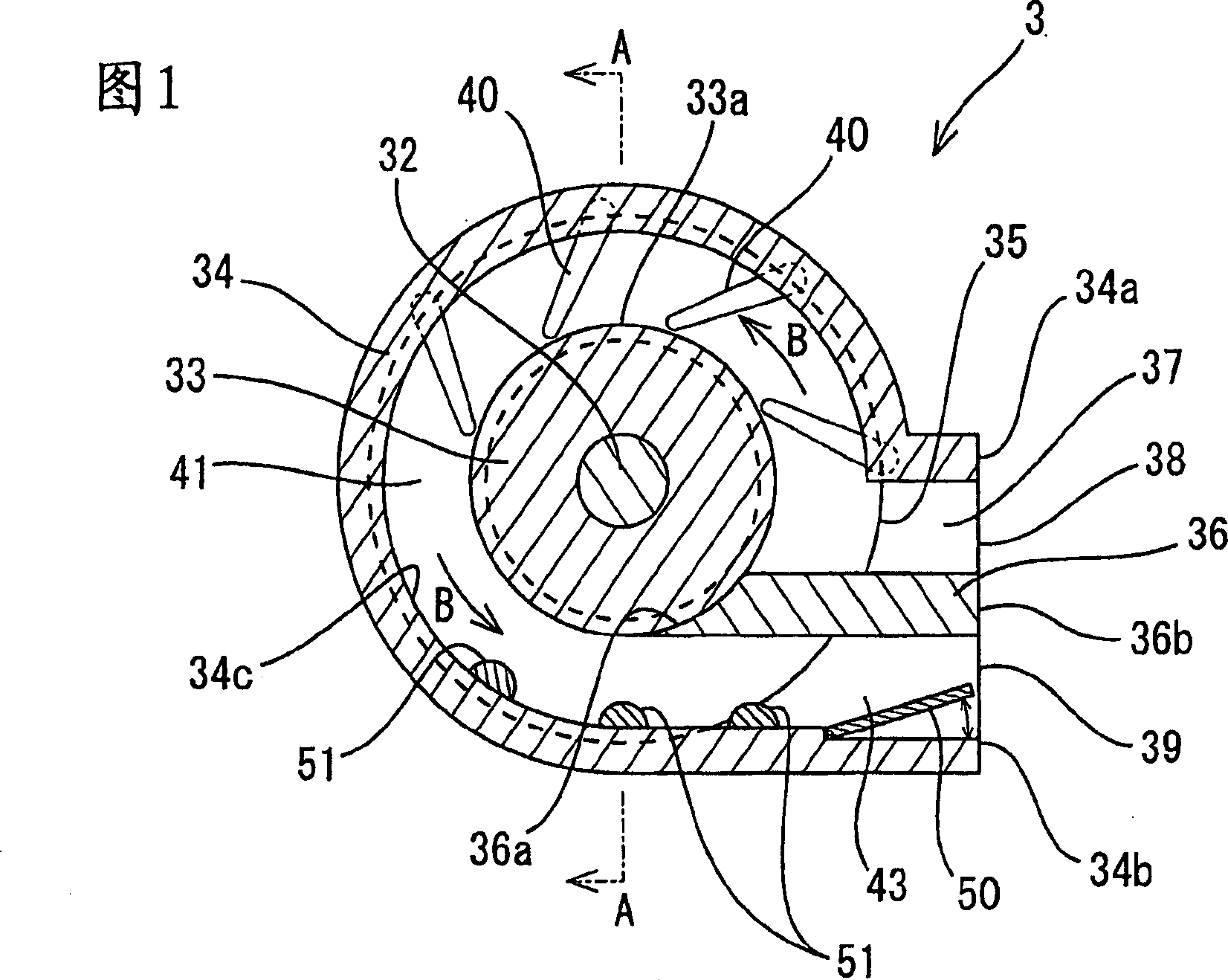
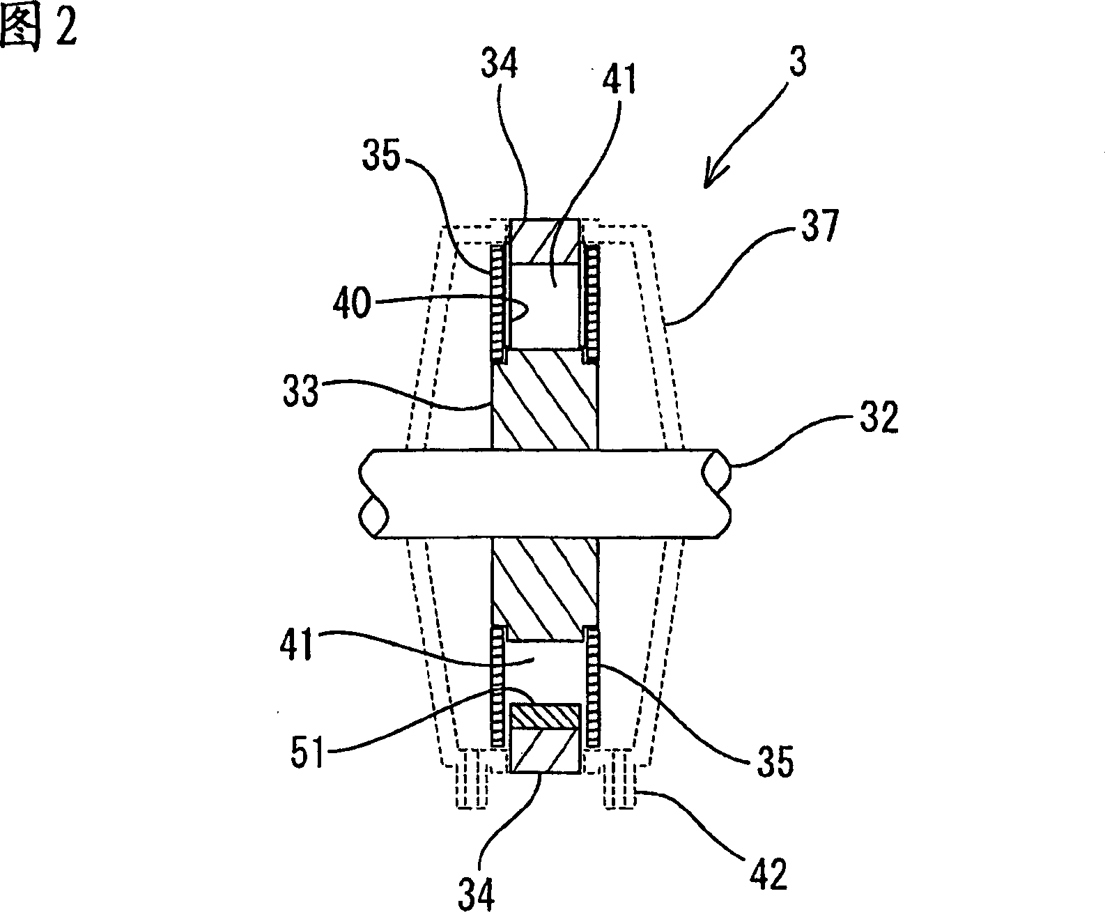
[0028] Hereinafter, embodiments of the present invention will be described with reference to the drawings. Fig. 1 is a cross-sectional view showing the basic structure of a high dehydration type rotary pressurized dehydrator 3 according to the present invention. FIG. 2 is a sectional view taken along line AA of the rotary pressurized dehydrator 3 shown in FIG. 1 . As shown in the figure, the rotary pressure dehydrator 3 consists of a rotating shaft 32, an inner ring bushing 33, an outer ring bushing 34, two annular sieves 35, a scraper 40, a guide 36, a raw material supply port 38, Filter cake outlet 39, back pressure plate 50, outer casing 37 etc. constitute.

[0029] In this rotary pressurization dehydrator 3 , when a driving force is supplied from a driving device not shown to rotate the rotating shaft 32 , the inner ring bushing 33 fixed around the rotating shaft 32 and the inner ring bushing 33 fixed The two sieves 35 on the top rotate together with the rotating shaft 3...


PUM


Abstract

A rotation pressurization dehydrator adapted to locally increase the compressive force on moving dehydrated cake so as to efficiently reduce the liquid content of its region for which dehydration has not been sufficient by a conventional rotation pressurization dehydrator, whereby in discharged, dehydrated cake, the difference in liquid content among regions is made small. In a rotation pressurization dehydrator (3) which, as a raw material advances in an annular filter chamber (41) formed around a rotary shaft (32), gradually applies a pressure to the material to change the liquid material into cake, thereby dehydrating the material, projections (51) are disposed on the inner peripheral surface (34c) of an outer ring spacer (34) so as to further reduce the liquid content of the dehydrated cake.

Description

technical field [0001] The invention relates to a device for filtering raw materials containing solids (treatment raw liquid), dehydrating, and separating solids from liquids, especially in the ring formed by rotating two circular sieves, inner ring bushings and outer ring bushings. In the filter chamber, there is a rotary pressurized dehydrator that can filter and dehydrate raw materials. Background technique [0002] Rotary pressure dehydrator (rotary pressure filter), for example, as shown in Japanese Patent Application Laid-Open No. 2001-113109, introduces raw materials into an annular filter chamber formed around the rotating shaft, and rotates an annular sieve to thereby Make the raw material move forward, pressurize gradually, and carry out dehydration treatment. [0003] FIG. 12 is a cross-sectional view of a conventional general rotary dehydrator 101 . As shown in the figure, the raw material is introduced into the filter chamber 110 from the raw material supply p...

Claims


Application Information

Patent Timeline
IPC IPC(8): B01D33/15B30B9/20
CPCB30B9/20B01D33/15B01D33/466B01D33/644
Inventor 矢野宰平
Owner TOMOE ENGINEERING CO LTD
Why Eureka
Try Eureka