Communications system and leakage optical fiber

A communication system and optical fiber technology, applied in the field of communication systems, can solve the problems of increasing or decreasing the refractive index diameter, large attenuation, slow communication speed, etc., and achieve the effect of stable optical waveform, accurate communication, and high-quality communication

Inactive Publication Date: 2007-04-04
NAKAGAWA LAB INC
View PDF1 Cites 4 Cited by
  • Summary
  • Abstract
  • Description
  • Claims
  • Application Information

AI Technical Summary

Problems solved by technology

[0003] However, the above-mentioned technology has the following disadvantages: the attenuation is large due to the use of high frequencies, and the communication speed is slow
However, in order to produce such an optical fiber, the second core 52 must be formed outside the intermediate core 51, or the refractive index must be increased or decreased in the longitudinal direction or the diameter must be changed, which is extremely difficult in terms of production.
[0012] As mentioned above, the technology of leaking communication information from the side of the communication line has been used for radio waves and light, but due to various problems in performance and manufacturing technology, a technology that can perform high-speed communication and is easy to manufacture has not yet been invented

Method used


Image

  • Communications system and leakage optical fiber
  • Communications system and leakage optical fiber
  • Communications system and leakage optical fiber

Examples


Embodiment Construction

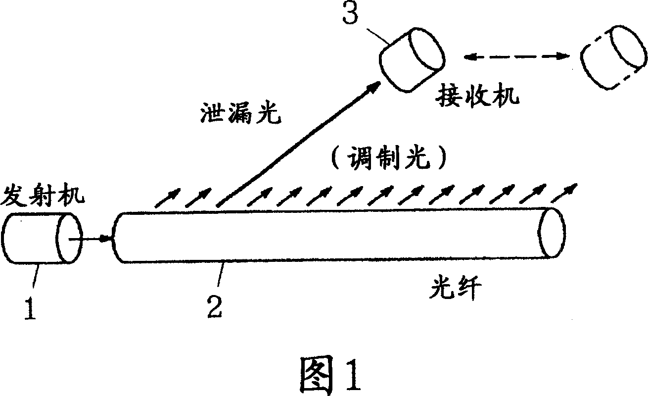
[0020] FIG. 1 is a conceptual diagram showing an embodiment of a communication system of the present invention. In the figure, 1 is a transmitter, 2 is an optical fiber, and 3 is a receiver. A transmitter 1 emits light modulated by transmitted information into an optical fiber 2 . For example, a laser diode (LD: Laser Diode) or the like can be used to emit laser light into the optical fiber 2 . Of course, the light source is not limited to a laser diode, and can be an LED, etc., as long as the light source can be controlled at high speed or turned off, it can be used as the light source of the transmitter 1 .

[0021] The optical fiber 2 is a GI-type optical fiber having a core, the refractive index of which is large at the center, and gradually decreases from the center to the periphery. In the communication system of the present invention, the light 2 can use the leaky optical fiber of the present invention in which scatterers are mixed into the GI type optical fiber to in...


PUM


Abstract

A communications system implementing a high-speed, high-quality communication in an oblong communication range such as communication with a mobile body or the like, and a leakage optical fiber suitably used in such a communications system. The optical fiber (2) is a GI type optical fiber having a core so constituted that a refractive index at its center is large and it is gradually reduced toward its periphery, and may permit the mixing of a scatterer. A modulation light sent from a transmitter (1) into the optical fiber (2) travels through the optical fiber (2) with part of it leaking from the side surface of the optical fiber (2). A receiver (3) receives this leaked light and demodulates it to capture information. Being of a GI type, the optical fiber (2) is small in waveform rounding and permits a high-speed, high-quality mobile communication.

Description

technical field [0001] The present invention relates to a communication system for communicating in a long and thin area (for example, communicating with a mobile body, etc.), and an optical fiber used in the communication system. Background technique [0002] As a technology for transmitting information (mobile communication, etc.) in a narrow communication area, for example, conventional technology uses a leaky coaxial cable (LCX: Leaky Coaxial Cable) to perform communication using radio waves. In the leaky coaxial cable, slits are periodically provided in the outer conductor of the coaxial cable, and a part of VHF charged waves propagating inside the cable are radiated to the outside. The radiated electric field is approximately circularly symmetrical, and the generated electric field is used to communicate within a limited range such as roads and railways around the cable. [0003] However, the above-mentioned technology has disadvantages in that the attenuation is larg...

Claims


Application Information

Patent Timeline
IPC IPC(8): H04B10/12G02B6/42H04B10/13H04B10/135H04B10/14G02B6/28H04B10/25
Inventor 春山真一郎菅原靖夫中川正雄小池康博石榑崇明铃木弘真志村彰洋
Owner NAKAGAWA LAB INC
Why Eureka
Try Eureka