
Swinging saw special for mandibular angle bone cutting

A technique of oscillating saw and osteotomy, which is applied in the direction of application, surgical saw, bone drill guidance, etc. It can solve the problems of blocking the surgical field of vision, inoperability, and troublesome surgery, and achieve good surgical results, easy operation, and accurate operation.

Inactive Publication Date: 2007-04-11
GENERAL EQUIP DEPT BEIJING HUANGSI COSMETIC SURGICAL HOSPITAL +2
View PDF0 Cites 6 Cited by
  • Summary
  • Abstract
  • Description
  • Claims
  • Application Information

AI Technical Summary

Problems solved by technology

[0002] Whether the mandibular angle of the human body protrudes and whether the protrusion is large or small directly determines the shape of the face. At present, in the medical cosmetology of the human face, it is often necessary to perform osteotomy on the mandibular angle. The tools used for the existing osteotomy are mainly swinging Saw, its structure is: there is a cylindrical saw bar with a length of 60mm-70mm, and a flat saw blade is fixed at one end of the saw bar. The angle is a right angle, the periphery of the saw blade is provided with sawtooth, and the other end of the saw rod is connected with a connecting end. When in use, connect the connecting end of the saw rod to the connecting head at one end of the handle. The output end is connected to the connector, and the input end of the transmission device is connected to the drive device through a flexible shaft. During the working process, the drive device drives the flexible shaft to rotate, and the flexible shaft drives the transmission device to run. The saw blade swings to achieve the purpose of osteotomy. The existing swing saw with this structure has the following disadvantages: because the angle between the plane where the saw blade is located and the center line of the saw bar is at right angles, and the saw bar is cylindrical and short, It is very inconvenient to extend into the oral cavity to saw the mandibular angle. The right angle is not suitable for the human mandibular angle, which blocks the surgical field of view. When amputating the mandibular angle and ascending ramus in a narrow surgical space, the maneuverability is extremely poor. Insufficiency, several calls can not be operated, which brings trouble to the operation; in order to solve the above problems, some use reciprocating saws to perform operations. Reciprocating movement, this method cannot perform surgery from the inside of the mouth, requires skin-assisted incision, and has exposed surgical traces, which is not an ideal surgical method

Method used


Image

  • Swinging saw special for mandibular angle bone cutting
  • Swinging saw special for mandibular angle bone cutting
  • Swinging saw special for mandibular angle bone cutting

Examples


Embodiment Construction

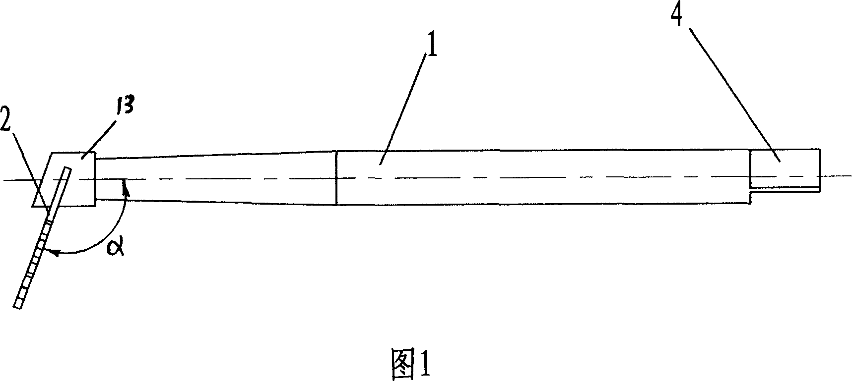
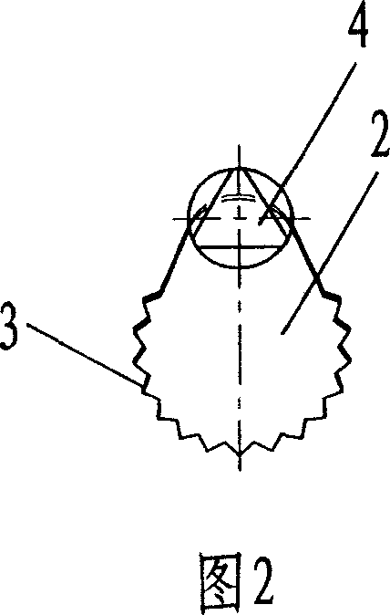
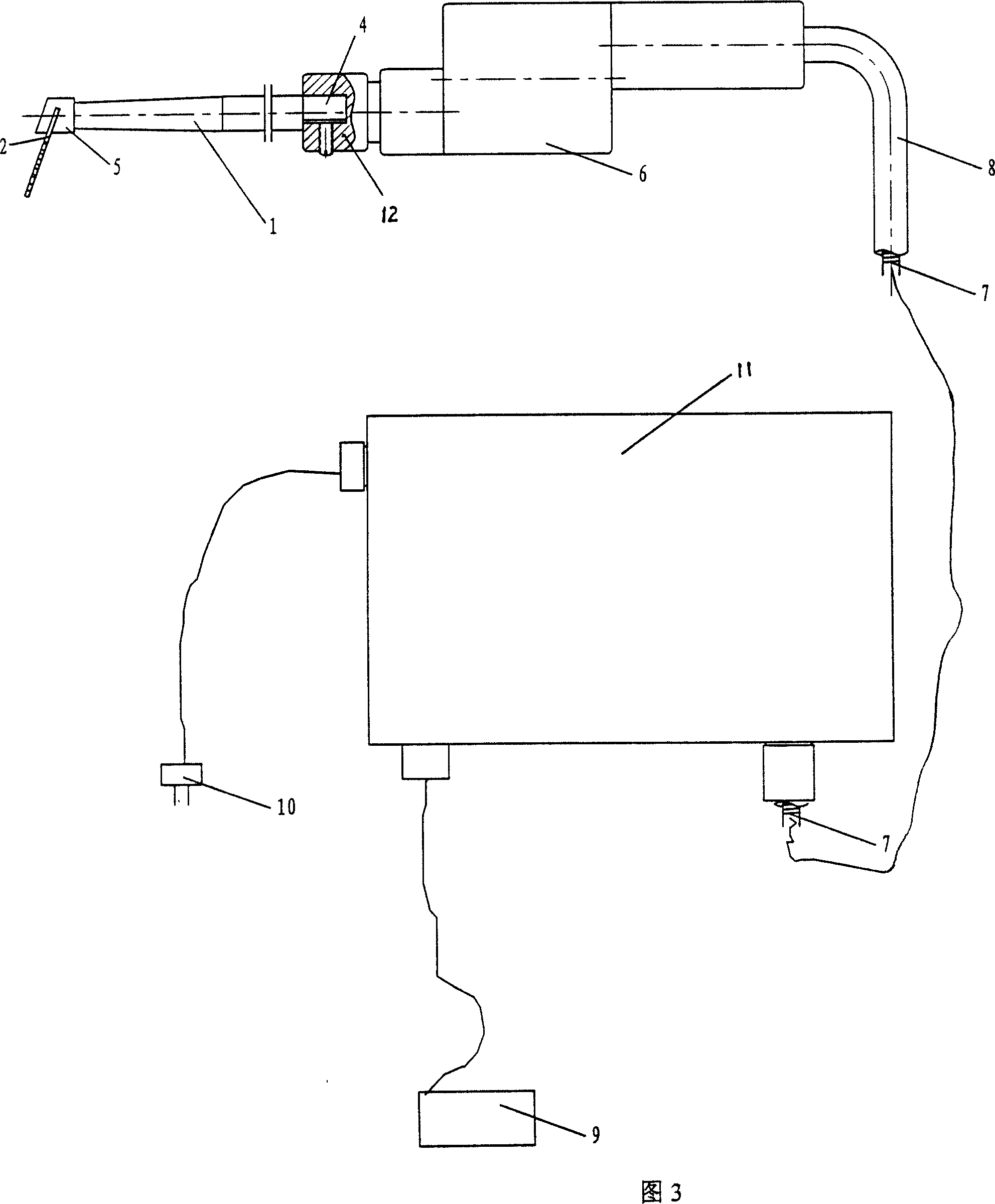
[0012] As shown in the figure: 1 is the saw bar, the right end of the saw bar 1 is the connecting end 4, the cross section of the connecting end 4 is triangular, the left end of the saw bar 1 is equipped with a saw blade 2, the saw blade 2 is flat, and The edge is arc-shaped and processed with sawtooth 3, the height of the sawtooth 3 is determined between 1.8mm-2.2mm, the top of the saw blade 2 is inserted in a connecting block 13, between the saw blade 2 and the connecting block 13, the connecting block All adopt welding mode to be fixedly connected between 13 and the end of saw bar 1. The degree of the included angle α formed by the plane where the saw blade 2 is located relative to the center line of the saw bar 1 is determined between 95°-115°. In order to suit each area of ​​the mandibular angle, the degree of the included angle α can be determined as 95° respectively , 100°, 105°, 110°, 115°, forming various swing saws with different angles. The front part of the saw ba...


PUM

PropertyMeasurementUnit
Degreeaaaaaaaaaa
Lengthaaaaaaaaaa
Height dimensionaaaaaaaaaa

Abstract

The invention discloses an instrument for cutting bones, particularly a special swaying saw for cutting bone on the corner of the lower jaw, mainly used for undertaking bone-cutting on the corner of the lower jaw within the oral cavity.

Description

technical field [0001] The invention relates to a medical osteotomy tool, in particular to a special oscillating saw for mandibular angle osteotomy, which is mainly used for performing osteotomy on the mandibular angle from the inside of the human oral cavity. Background technique [0002] Whether the mandibular angle of the human body protrudes and whether the protrusion is large or small directly determines the shape of the face. At present, in the medical cosmetology of the human face, it is often necessary to perform osteotomy on the mandibular angle. The tools used for the existing osteotomy are mainly swinging Saw, its structure is: there is a cylindrical saw bar with a length of 60mm-70mm, and a flat saw blade is fixed at one end of the saw bar. The angle is a right angle, the periphery of the saw blade is provided with sawtooth, and the other end of the saw rod is connected with a connecting end. When in use, connect the connecting end of the saw rod to the connectin...

Claims


Application Information

Patent Timeline
IPC IPC(8): A61B17/14A61B17/94
Inventor 汪立川张旭东
Owner GENERAL EQUIP DEPT BEIJING HUANGSI COSMETIC SURGICAL HOSPITAL
Learn More