Positioning device for mandibular ramus osteotomy

A positioning device and mandible technology, which is applied in the direction of surgery, stereotaxic surgical instruments, bone drill guidance, etc., can solve the problems of increasing the economic burden of patients, difficult identification of landmarks, low accuracy and efficiency, and achieve economic relief. Burden, reduction of operation time, effect of convenient combination

Active Publication Date: 2016-03-16
SICHUAN UNIV
View PDF4 Cites 3 Cited by
  • Summary
  • Abstract
  • Description
  • Claims
  • Application Information

AI Technical Summary

Problems solved by technology

Clinically, the lateral prominence of the mandibular ramus is often used as the positioning mark of the surgical osteotomy line, but because the lateral prominence of the mandibular ramus is located anteriorly and superiorly to the inner mandibular nerve foramen, the resolution of the naked eye is low, and Some patients do not have the lateral prominence of the mandibular ramus, so there are certain limitations in using it as a positioning marker for the surgical osteotomy line
Moreover, in such a narrow operative field and space, the landmarks are difficult to identify, and it is inconvenient for the operator to place the oscillating saw and perform the osteotomy at the expected position. The operator can only rely on the operator's feeling and experience, and the accuracy and efficiency are low.
[0004] Chen Xiayun et al. made a 3D-printed personalized osteotomy guide plate surrounding the posterior edge of the ascending ramus to guide the osteotomy (see "Research on the accuracy and clinical application of computer-aided design of individualized templates in vertical mandibular ramus osteotomy via intraoral approach" , Chen Xiayun, etc., Chinese Journal of Stomatological Research (Electronic Edition), 2009, Vol.3, No.6), but the osteotomy guide plate needs to be stripped off too much muscle and surrounding tissue at the posterior edge of the ascending ramus and the lower edge, It is not easy to position during the operation, and each patient needs to customize an osteotomy guide plate, which increases the economic burden of the patient

Method used


Image

  • Positioning device for mandibular ramus osteotomy
  • Positioning device for mandibular ramus osteotomy
  • Positioning device for mandibular ramus osteotomy

Examples


Embodiment 1

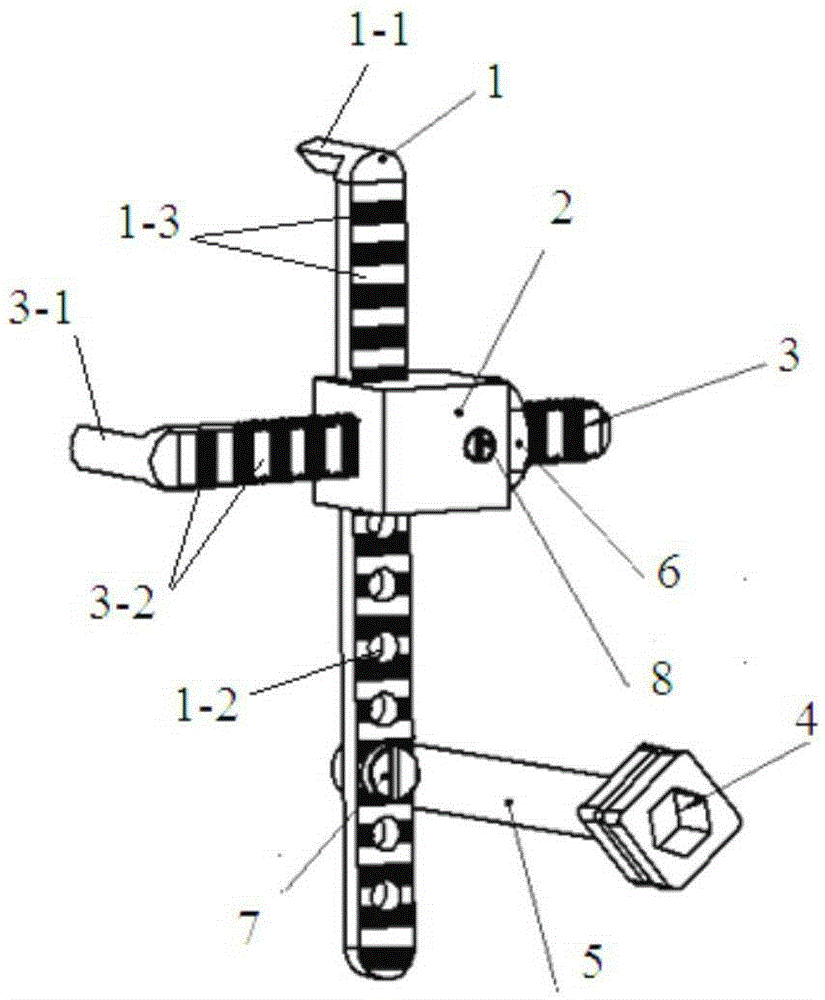
[0050] The mandibular ramus osteotomy positioning device described in this embodiment is as follows: figure 1 , figure 2 As shown, it includes a first main rod 1, an auxiliary rod 3, a first connector 2, a positioning rod 5, a first stopper 6 and an intraosseous nail 4 for fixing during operation.

[0051] The first main rod 1 is a rod with a rectangular cross section, the back of the upper end of the first main rod is provided with an upper edge hook 1-1 positioned at the sigmoid notch 16-5 of the ascending ramus of the mandible, and the front is provided with a length Indicating marks 1-3, the lower section is provided with holes for installing positioning rods, the length indicating marks are 1mm wide strip marks with alternating light and dark, and the holes for installing positioning rods are multiple centerlines on a straight line and Circular holes 1-2 with equal spacing; the auxiliary rod 3 is a screw rod whose cross-section is surrounded by two parallel lines with t...

Embodiment 2

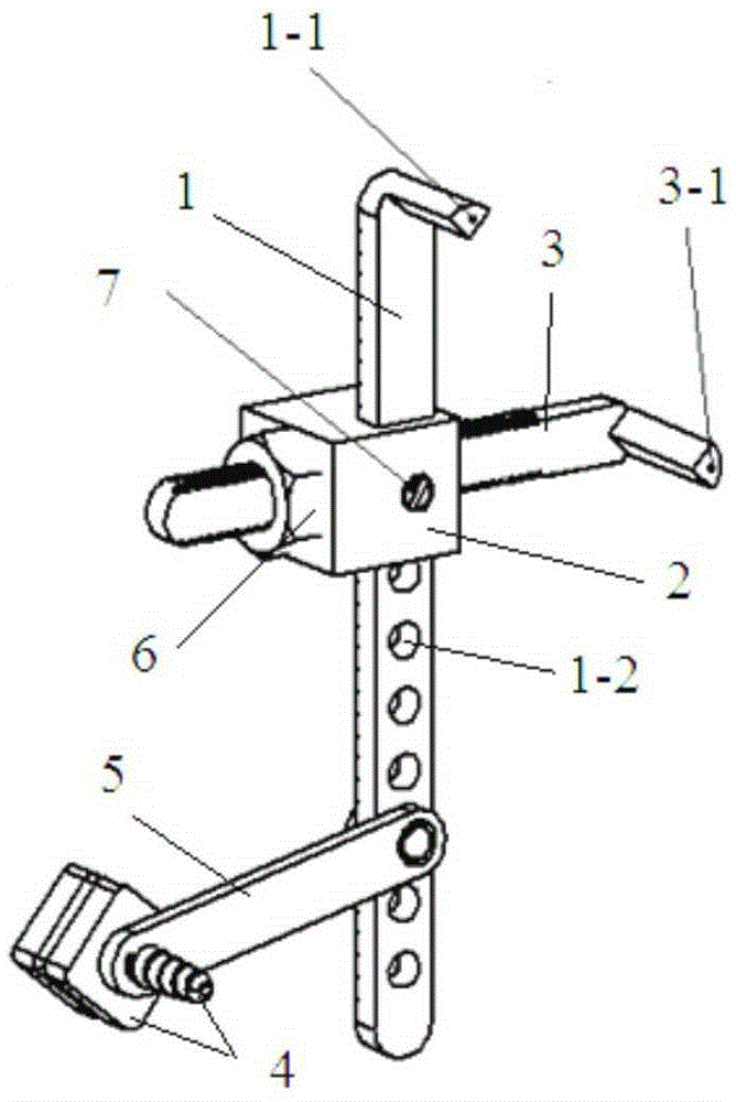
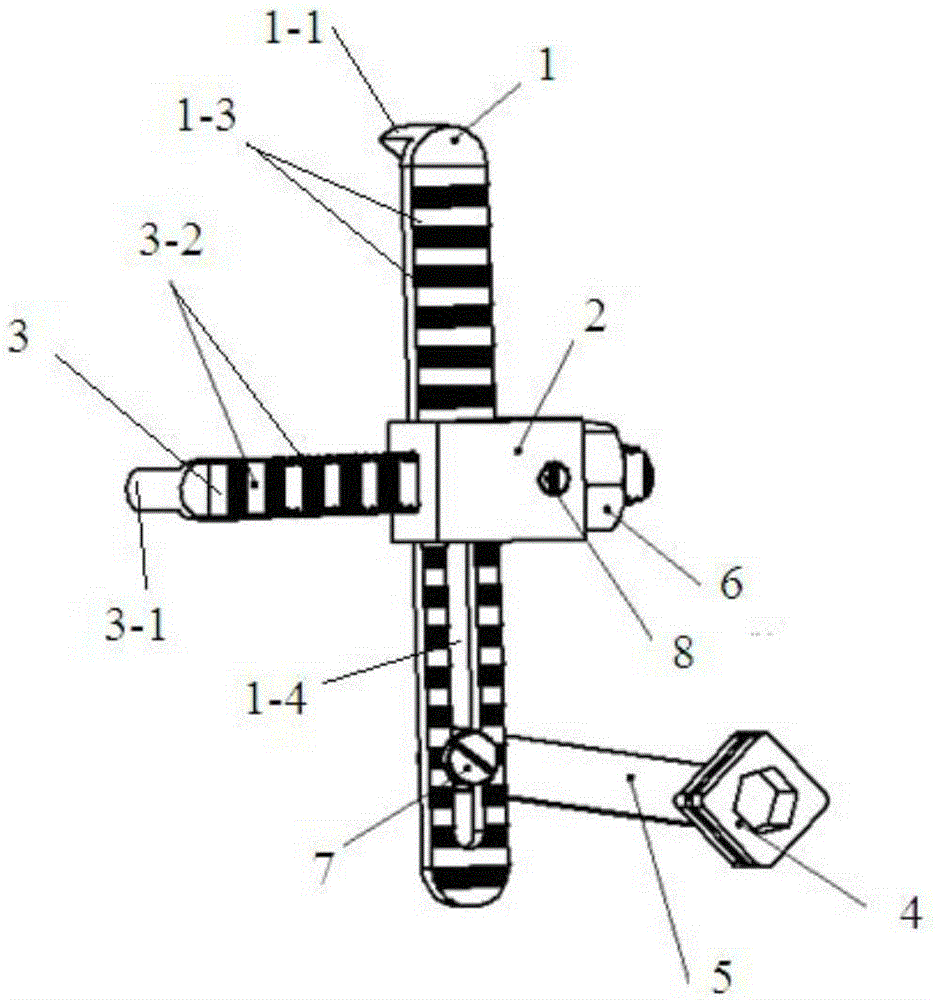
[0063] The mandibular ramus osteotomy positioning device described in this embodiment is as follows: image 3 , Figure 4 As shown, it includes a first main rod 1, an auxiliary rod 3, a first connector 2, a positioning rod 5, a first stopper 6 and an intraosseous nail 4 for fixing during operation. The difference from Embodiment 1 is that the holes provided on the lower section of the first main rod for installing the positioning rod are bar-shaped holes 1-4.

[0064] For the usage method of the mandibular ramus osteotomy described in this embodiment, see Figure 17 , the same as in Example 1.

Embodiment 3

[0066] The mandibular ramus osteotomy positioning device described in this embodiment is as follows: image 3 , Figure 4 As shown, it includes a second main rod 17, a guide plate 9, a first strut 10, a second strut 13, a second limiter 11, a third limiter 14, a second connector 12, and a third connector 15 And the intraosseous nail 4 that plays a fixed role during the operation.

[0067]The second main rod 17 is a rod with a rectangular cross section, the back of the upper end of the second main rod is provided with an upper edge hook 17-1 positioned at the sigmoid notch 16-5 of the ascending ramus of the mandible, and the lower end is provided with a The hole combined with the intraosseous nail is provided with a length indicating mark 17-2 on the front, and the hole combined with the intraosseous nail is a unidirectional stress hole composed of a semicircular hole 17-3 and a semiconical hole 17-4, and the length indicates The logo is a 1.5mm wide strip logo with alternati...


PUM


Abstract

The invention discloses a positioning device for a mandibular ramus osteotomy. The positioning device has two structures: according to the first structure, the positioning device comprises a first main rod, a subordinate rod, a first connector, a positioning rod, a first limiter and an intra-bone nail which takes a fixing effect during an operation; and according to the second structure, the positioning device comprises a second main rod, a guide plate, a first branch rod, a second branch rod, a second limiter, a third limiter, a second connector, a third connector and an intra-bone nail which takes a fixing effect during the operation. When the positioning device is used, an operation incision line can be kept away from mandibular nerve and mandibular nerve tube, and the location of an osteotomy line can be directly and accurately determined; and during the operation, injury of inferior alveolar nerve vessel bundles can be avoided, and a sufficient width with proximal segment can be guaranteed as well.

Description

technical field [0001] The invention belongs to the field of auxiliary medical devices, in particular to a positioning device for mandibular ramus osteotomy. Background technique [0002] The vertical ramus of mandibular ramus (IVRO) or oblique osteotomy (IORO) via intraoral approach adopts the mucoperiosteal incision at the anterior edge of the ramus to expose the lateral surface of the ramus of the mandible, downward from the sigmoid notch of the ramus of the mandible, Complete incision of the ascending ramus full-thickness bone through the back of the mandibular nerve foramen to the front of the mandibular angle is widely used in the correction of mandibular protrusion and severe mandibular asymmetry, especially for preoperative temporomandibular joint disorder syndrome (TMJD) patients can significantly reduce symptoms. Only a single osteotomy line is used with this technique, so the operation is relatively simple, the time is short, the bleeding is less, and the bone tr...

Claims


Application Information

Patent Timeline
Patent Type & Authority Applications(China)
IPC IPC(8): A61B17/16A61B17/17A61B90/14
CPCA61B17/1657A61B17/1673A61B17/1732A61B17/176
Inventor 祝颂松叶斌刘斌刘振华胡静刘晓光
Owner SICHUAN UNIV
Why Eureka
Try Eureka