Real time detecting device and method for optical glass roughness

An optical glass, real-time detection technology, applied in the direction of using optical devices, measuring devices, instruments, etc., can solve the problem of high precision machining and manufacturing is not suitable

Inactive Publication Date: 2007-04-11
SHANGHAI INST OF OPTICS & FINE MECHANICS CHINESE ACAD OF SCI
View PDF1 Cites 17 Cited by
  • Summary
  • Abstract
  • Description
  • Claims
  • Application Information

AI Technical Summary

Problems solved by technology

[0004] In the existing technology, most of the real-time measurement of the surface roughness of the workpiece uses destructive testing, b...

Method used


Image

  • Real time detecting device and method for optical glass roughness
  • Real time detecting device and method for optical glass roughness
  • Real time detecting device and method for optical glass roughness

Examples


Embodiment Construction

[0037] The present invention will be further described below in conjunction with accompanying drawings and real-time examples.

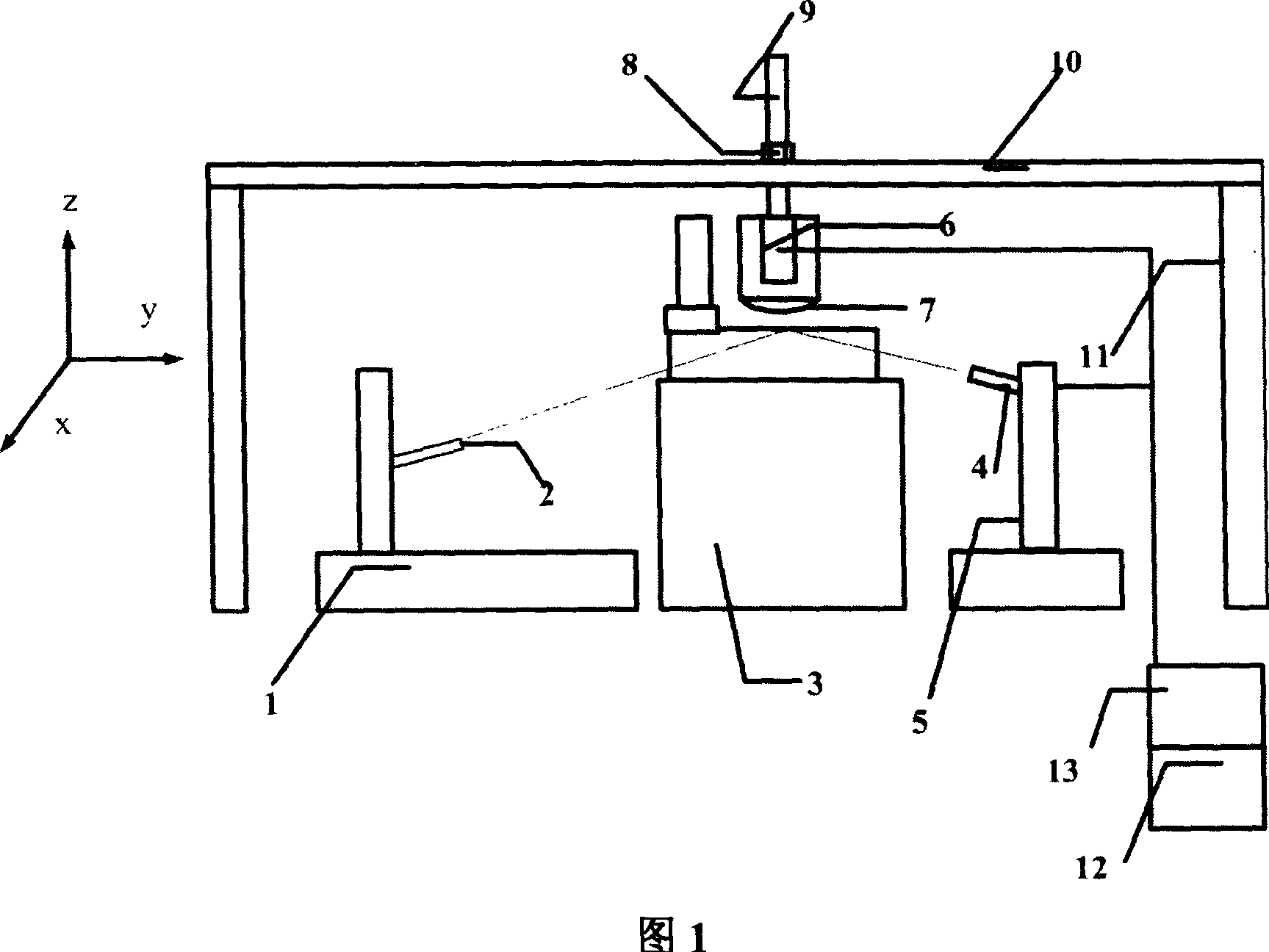
[0038] Please refer to FIG. 1 first. FIG. 1 is a schematic structural diagram of a preferred embodiment of a real-time detection device for roughness of optical glass according to the present invention. As can be seen from the figure, the present invention is used for the real-time detection device of the optical glass roughness of optical polishing machine, comprises the optical glass workpiece to be processed that places on a polishing machine 3, is characterized in that comprising:

[0039] A guide rail beam 10 is fixed on a bracket 11 parallel to the ground, and a lifting screw 9 is vertically provided on the guide rail beam 10 through a matching lifting nut 8, and the lifting screw 9 can move horizontally along the guide rail of the guide rail beam 10 and pass through The height of the lifting nut 8 is adjusted. The first light intensity detecto...


PUM


Abstract

The present invention is real-time roughness detecting device and method in optical glass polishing machine. By means of laser surface scattering principle, the incident angle of laser source beam to the measured optical glass surface is regulated to greater than or equal to the total reflection angle so as to separate scattered light from the reflected light, and the strengths of these two light beams are measured separately and converted into current strengths and the current strength ratio of these two light beams is calculated to calculate the roughness of the measured surface precisely. The present invention is non-destructive test, and has no damage to the tested workpiece and high detection precision.

Description

technical field [0001] The invention relates to optical glass, and relates to a real-time detection device and method for the roughness of the optical glass, in particular to a real-time detection device and method for the roughness of the optical glass used in an optical polishing machine. Background technique [0002] In the patent "A Method and Device for Detecting Surface Roughness" (Patent Publication No. CN1081250), a method for measuring surface roughness is introduced in detail. Cut the bright band image for edge detection to obtain the edge contour coordinate points and roughness parameters in pixels within a sampling length, and perform unit conversion according to the calibration to obtain surface roughness parameters within a sampling length. The device using this method is made on the basis of the light section microscope by adding components such as an image sensor, an image acquisition device, a calculation and control device, and the like. [0003] A major d...

Claims


Application Information

Patent Timeline
IPC IPC(8): G01B11/30
Inventor 程骅沈卫星
Owner SHANGHAI INST OF OPTICS & FINE MECHANICS CHINESE ACAD OF SCI
Why Eureka
Try Eureka