Sanding device for rail vehicles

A sand spreading device and rail vehicle technology, applied in the layout of pipelines, vehicle components, wheels, etc., can solve the problems of damage signal transmission, accidents, and inability to carry out signal transmission, etc.

Inactive Publication Date: 2007-04-11
KNORR BREMSE SYST FUR SCHIENENFAHRZEUGE GMBH
View PDF2 Cites 12 Cited by
  • Summary
  • Abstract
  • Description
  • Claims
  • Application Information

AI Technical Summary

Problems solved by technology

The deterioration of the electrical conductance between the wheel and the track poses a risk, since the signal transmission can be impaired in the worst case due to poor maintenance of the track equipment, so that in the worst case the signal transmission cannot be carried out, or errors occur, which can lead to accidents

Method used


Image

  • Sanding device for rail vehicles
  • Sanding device for rail vehicles

Examples


Embodiment Construction

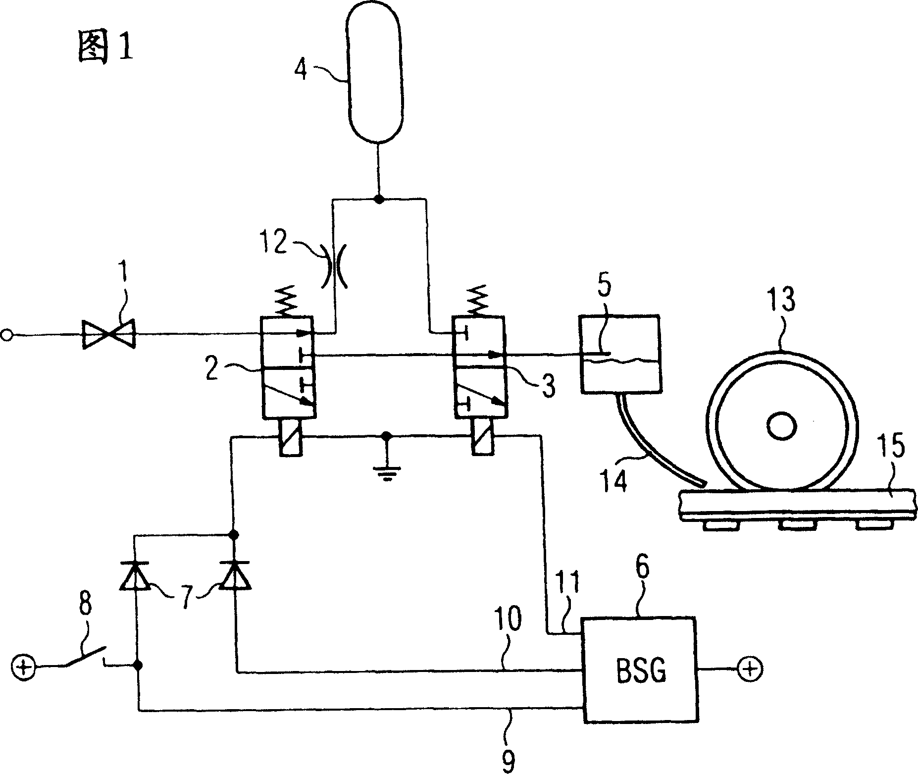
[0021] An embodiment of a sand spreading device designed according to the invention is shown in FIG. 1 .

[0022] The sand spreading device according to the invention mainly comprises a pressure reducing valve 1, a first pneumatic valve 2 in the form of a two-position three-way reversing valve 2, on which the pressure that is present in the pneumatic brake of the rail vehicle acts. A second two-position three-way reversing valve 3, a pressure vessel 4, a sanding nozzle 5 and a brake controller 6, the sanding nozzle is arranged in a sand container.

[0023] The outlet of the pressure reducing valve 1 is connected with the inlet of the first two-position three-way reversing valve 2 . One of the two outlets of the first 3 / 2 directional control valve 2 is connected to the connection of the pressure vessel 4 via a throttle valve 12 . The connection of the pressure vessel 4 is connected to one of the two inlets of the second 3 / 2-way valve 3 . The other outlet of the first two-posi...


PUM


Abstract

The invention relates to a sanding device for a rail vehicle, said device comprising a compressed air supply (1), a first pneumatic valve (2), a second pneumatic valve (3), a pressure container (4), and a sanding nozzle (5) in a sand container. The aim of the invention is to provide a rail region (15) beneath a wheel (13) of a rail vehicle with sand from a sand container. To this end, the sand container is fed with compressed air directly from the pressure container (4), automatically pulsed compressed air being guided from the compressed air supply (1) to the pressure container (4).

Description

technical field [0001] The invention relates to a sand spreading device for vehicles, in particular rail vehicles. To improve the coefficient of adhesion between the wheels and the road in adverse road conditions, the vehicle is equipped with a sanding device. It is the sanding device on the rail vehicle that helps to greatly increase the coefficient of adhesion between the wheel and the track for a short time during emergency braking. Background technique [0002] Here sand is sprinkled in front of the wheels so that the rail vehicle rolls on the "sanded" track with a greatly increased coefficient of adhesion. The effect of sanding here depends on the amount of sanding per unit distance traveled. Ideally a constant amount of sand should be spread per meter of travel. If too little sand is spread, the best effect of increasing the adhesion coefficient cannot be achieved. On the contrary, if too much sand is spread, the best effect cannot be obtained. [0003] But someti...

Claims


Application Information

Patent Timeline
Patent Type & Authority Applications(China)
IPC IPC(8): B60B39/08B61H11/00B60T17/04
CPCB60B39/023B60B39/086
Inventor R·克诺斯
Owner KNORR BREMSE SYST FUR SCHIENENFAHRZEUGE GMBH
Why Eureka
Try Eureka