
Active flow control for wind turbine blades

A flow control, wind turbine technology, applied in the direction of wind engine control, machine/engine, engine, etc., can solve the problems of rated power limitation, limiting the number of wind turbine power output, etc.

Inactive Publication Date: 2007-04-18
GENERAL ELECTRIC CO
View PDF0 Cites 8 Cited by
  • Summary
  • Abstract
  • Description
  • Claims
  • Application Information

AI Technical Summary

Problems solved by technology

Flow separation in these larger areas limits the amount of power output a wind turbine can produce below rated power
Blades with an elongated flat face are also limited by power rating for the same reason

Method used


Image

  • Active flow control for wind turbine blades
  • Active flow control for wind turbine blades
  • Active flow control for wind turbine blades

Examples


Embodiment Construction

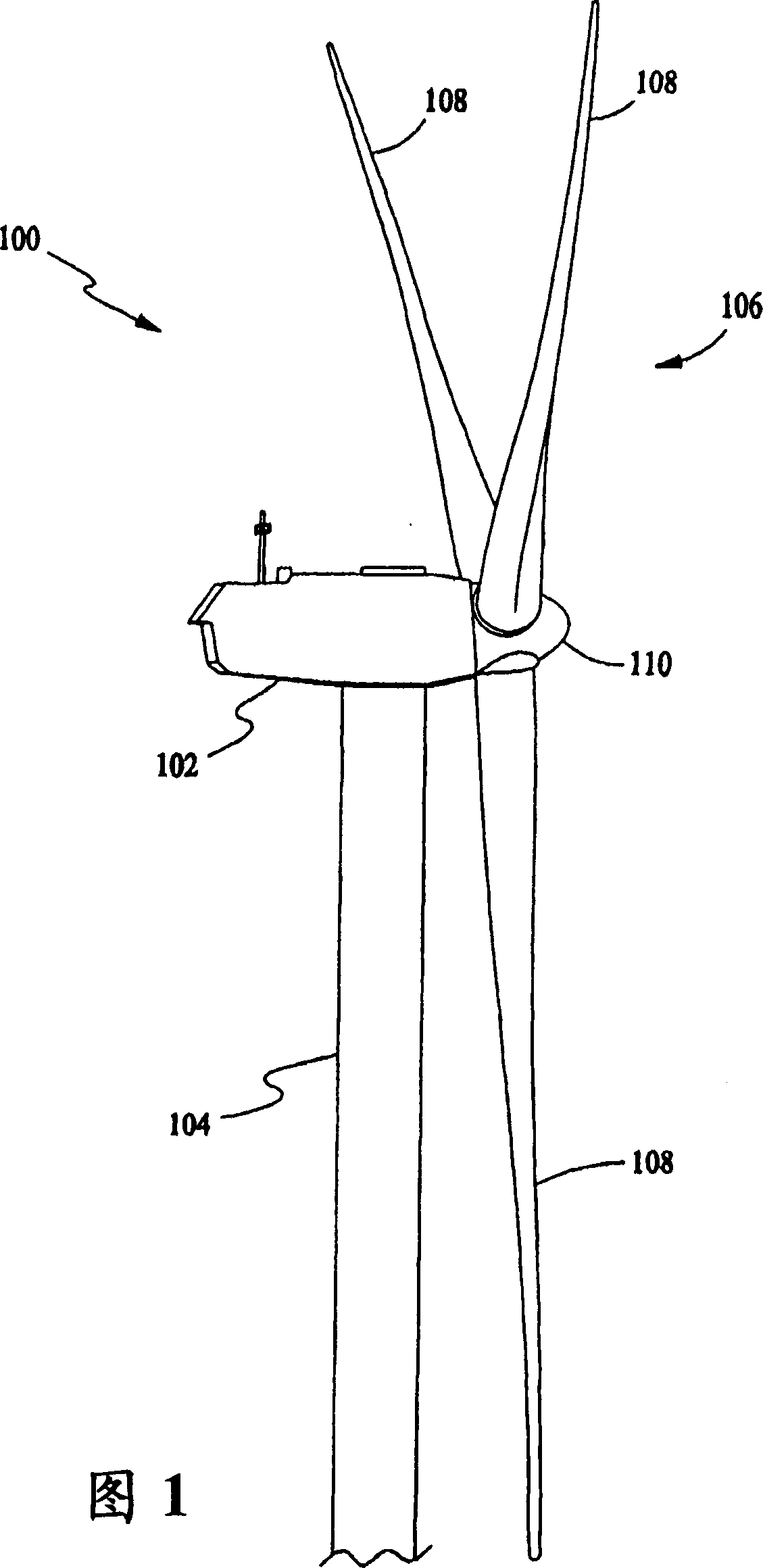
[0038] In certain constructions and referring to FIG. 1 , wind turbine 100 includes a nacelle 102 in which is housed a generator (not shown in FIG. 1 ). The nacelle 102 is mounted on top of a tower 104, only a portion of which is shown in FIG. 1 . The wind turbine 100 also includes a rotor 106 on which are disposed one or more rotor blades 108 connected to a rotating bushing 110 . Although wind turbine 100 shown in FIG. 1 includes three rotor blades 108 , the invention does not require a specific limitation on the number of rotor blades 108 .

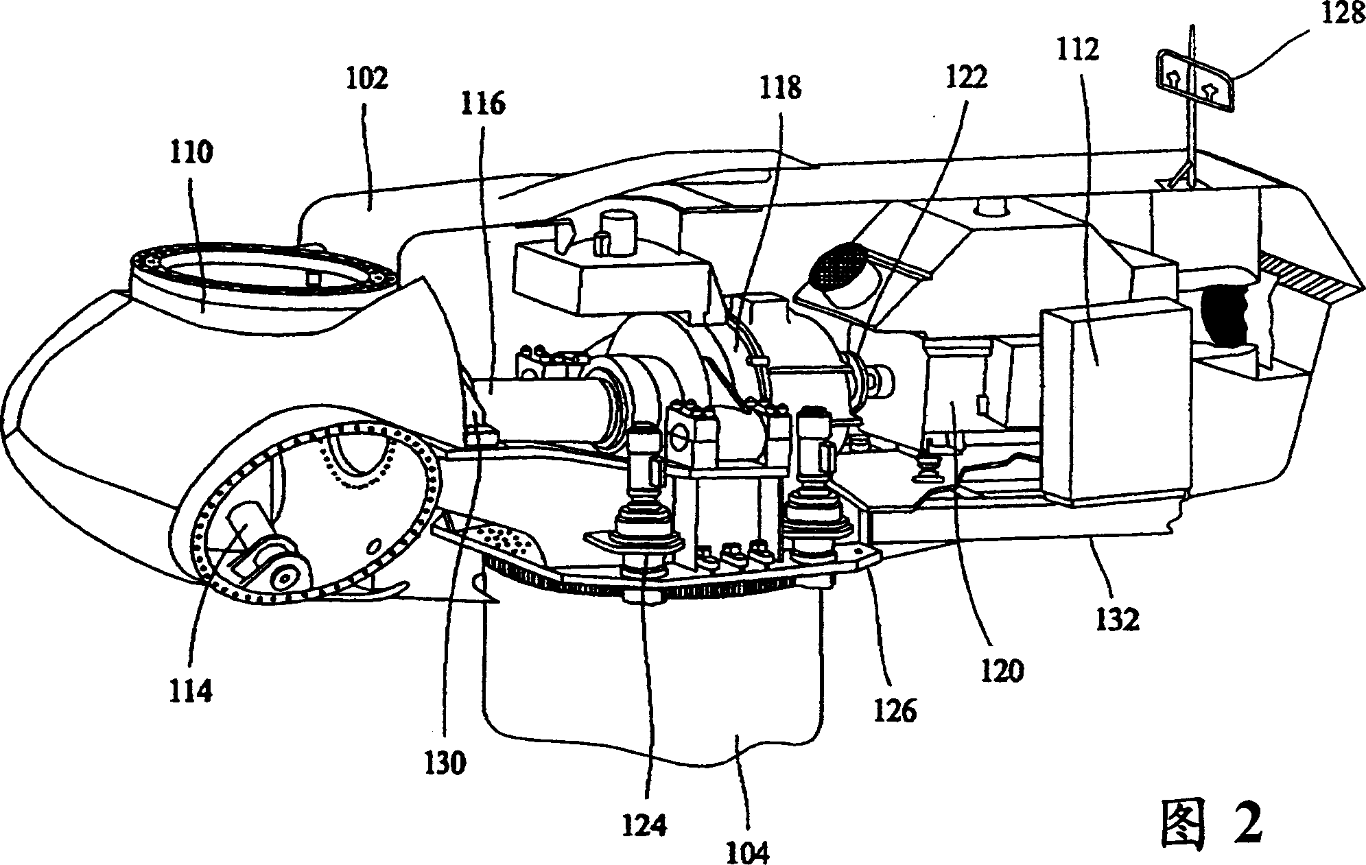
[0039] In certain constructions and referring to FIG. 2 , various components are housed in a nacelle 102 atop a tower 104 of the wind turbine 100 . The height of the tower 104 is selected based on factors and conditions known in the art. In some constructions, one or more microcontrollers within controller 112 comprise the control system for overall system monitoring and control. Different distribution or central control system confi...


PUM


Abstract

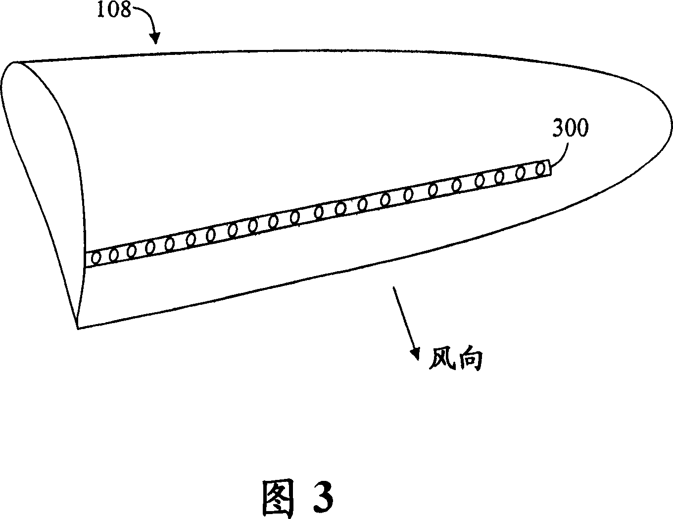
A wind turbine (100) with at least one blade (108) having an active flow control actuator (300) configured to increase an angle of attack range in which the blade or blades can generate torque without flow separation, using the flow control actuator to adjust this angle of attack range in accordance with load.

Description

technical field [0001] The present invention relates generally to wind turbines, and more particularly to methods and apparatus for enhancing the power output of wind turbines. Background technique [0002] In recent years, wind turbines have received increasing attention because they are environmentally friendly and a relatively inexpensive alternative energy source. With increasing interest, great efforts have been made to develop reliable and efficient wind turbines. [0003] Generally, a wind turbine includes a rotor with a plurality of blades. The rotor is mounted to a casing or nacelle, and the casing sits on a frame or tubular tower. Utility grade wind turbines (ie, wind turbines designed to provide electrical power to an application network) may be provided with large rotors (eg, 70 meters in diameter or larger). Blades on such a rotor convert wind energy into a rotational moment or force that drives one or more generators that are rotatably connected to the rotor...

Claims


Application Information

Patent Timeline
Patent Type & Authority Applications(China)
IPC IPC(8): F03D11/00F03D7/00
CPCF03D7/024Y02E10/723F03D1/0633F03D7/022F05B2240/32F05B2240/31F05B2240/301Y02E10/721F03D7/0256Y02E10/72
Inventor S·赫尔P·吉古雷A·古普塔
Owner GENERAL ELECTRIC CO
Learn More