

Rotation control device, rotation control method, and construction machine
A technology of a rotation control device and a control method, which is applied to electric speed/acceleration control, cranes, earth movers/shovels, etc., and can solve the problems of moving to the bottom and not being completely stationary.
- Summary
- Abstract
- Description
- Claims
- Application Information
AI Technical Summary
Problems solved by technology
Method used
Image

Examples
no. 1 Embodiment approach
[0032] [1-1] Overall composition
[0033] Hereinafter, a first embodiment of the present invention will be described with reference to the drawings.
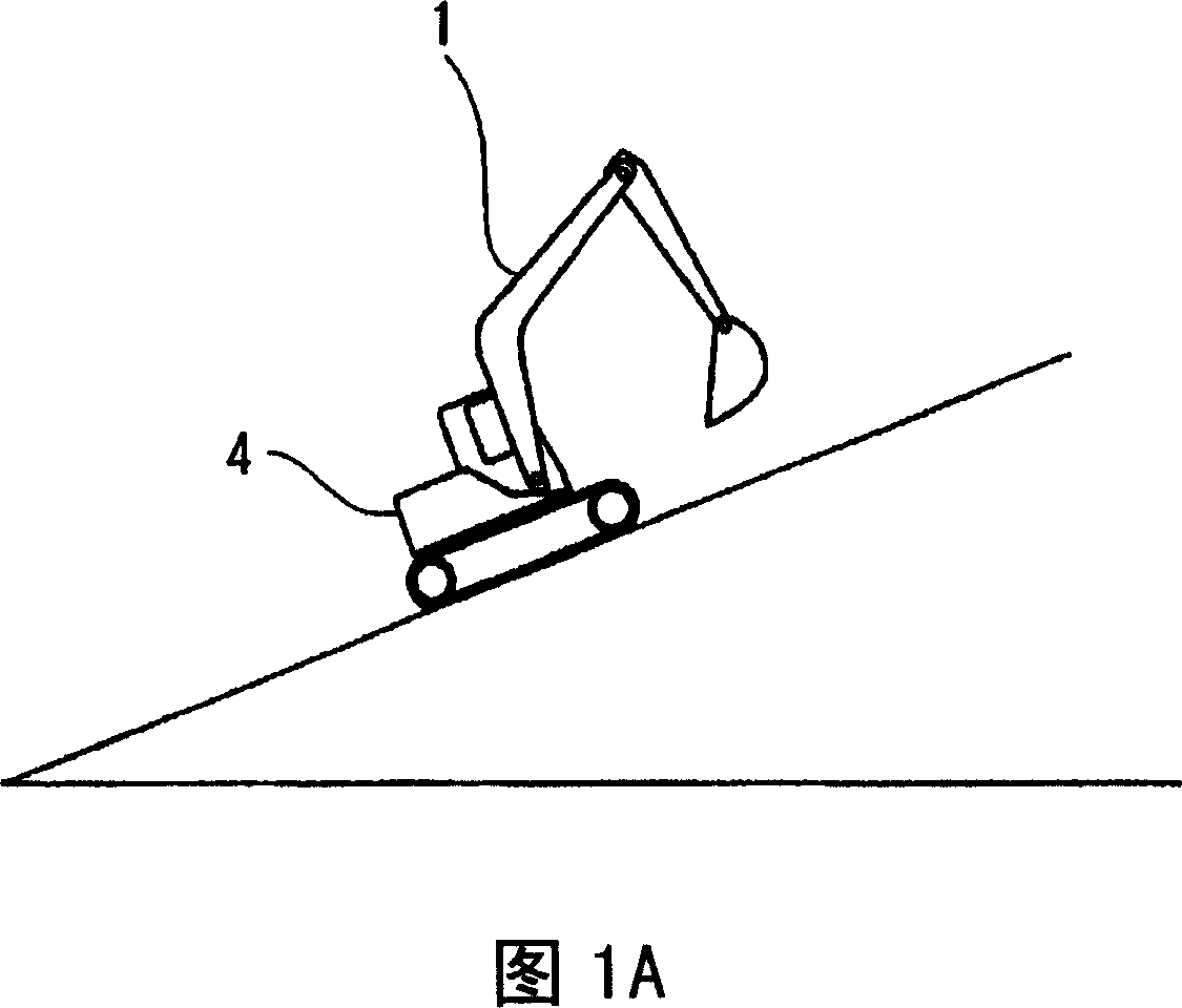
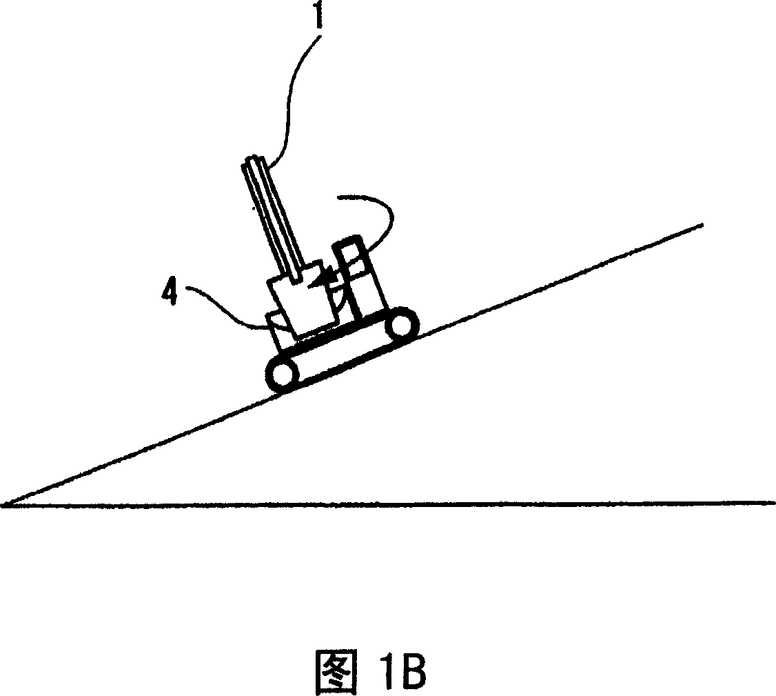
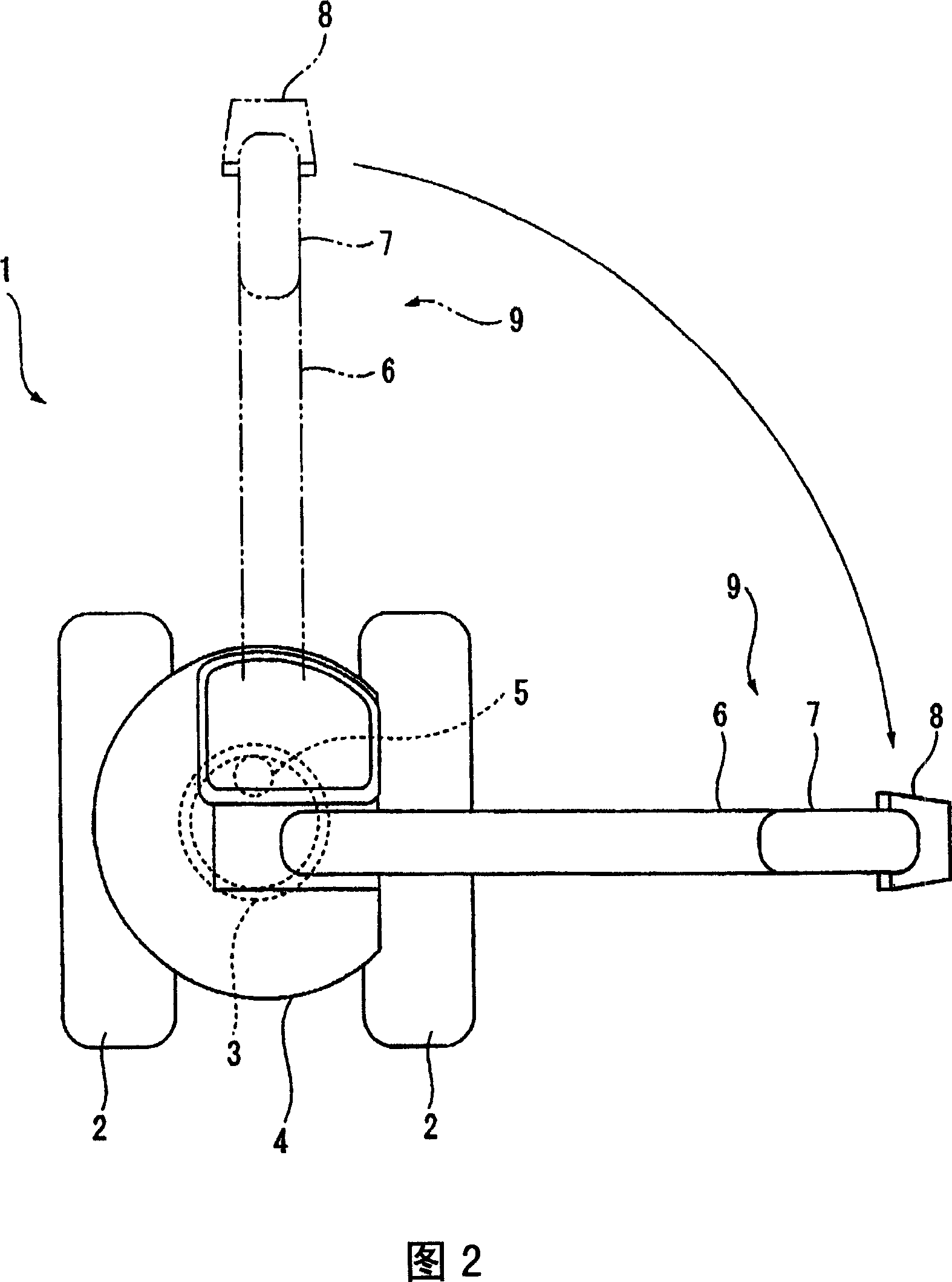
[0034] 1A is a schematic diagram showing a state in which the electric rotary shovel (construction machine) 1 according to this embodiment is arranged with the front of the rotary body 4 facing upward on the slope, and FIG. B shows that the rotary body 4 is rotated downward, and It is a schematic diagram of a state where it is stopped halfway (approximately 90° position, refer to FIG. 2 ). FIG. 2 is a plan view schematically showing the electric rotary shovel 1 . In addition, FIG. 3 is a block diagram showing the overall configuration of the electric rotary shovel 1 , and FIG. 4 is a diagram for explaining control of the rotary body 4 in the electric rotary shovel 1 .
[0035] In Fig. 1A, Fig. 1B and Fig. 2, the electric rotary shovel 1 is equipped with a revolving body 4, which is arranged on a track frame (track frame) const...
no. 2 Embodiment approach
[0075] FIG. 8 shows a second embodiment of the present invention.
[0076] In this embodiment, the control system change unit 150 of the rotation control device 100 switches the control law of the control command generation unit 130 from the speed control of the P control to the PI (Proportional Integral : Speed control of proportional integral) control. Therefore, since position control is not performed in this embodiment, the rotational position output means, reference position storage means, and reference position storage means update means in the first embodiment are not provided. Other configurations are the same as those of the first embodiment.
[0077] According to this embodiment, since the deviation between the target speed and the actual speed after the target speed reaches "0" is regarded as a residual deviation in speed control under normal P control, the actual speed does not become "zero" of the target speed. 0", it is difficult to maintain a static state, b...
no. 3 Embodiment approach
[0080] 9 and 10 show a third embodiment of the present invention.
[0081] The control structure of the rotation control device 100 in this embodiment, as shown in FIG. .
[0082] In this embodiment, instead of switching the control law of the control command generator 130 , as shown in FIG. 10 , the speed gain K, which is the control gain, is switched to a larger value to maintain the stationary state of the rotating body 4 . Therefore, in the control gain storage means 190, a plurality of speed gains of the rotating body 4 used for switching the speed gain at this time are stored.
[0083] In addition, in this embodiment, as shown in FIG. 9 , an operation state determination mechanism 170 is provided to determine whether the operation amount of the rotary control lever 10 is "0", that is, whether it is in the neutral position. Accordingly, it is determined whether or not the operator's operation is an operation for reliably stopping the rotating body 4 .
[0084] In additio...
PUM
 Abstract
Description
Claims
Application Information