Wind turbine for generating electricity

A technology for turbines and wind power generation systems, which is applied to wind power generator components, engines, engine components, etc., and can solve problems such as reducing the efficiency of converting kinetic energy into electrical energy

Inactive Publication Date: 2007-04-18
WIND ENERGY GRP INC
View PDF0 Cites 12 Cited by
  • Summary
  • Abstract
  • Description
  • Claims
  • Application Information

AI Technical Summary

Problems solved by technology

However, the gearbox can severely reduce the efficiency of converting kinetic energy into electrical energy

Method used


Image

  • Wind turbine for generating electricity
  • Wind turbine for generating electricity
  • Wind turbine for generating electricity

Examples


Embodiment Construction

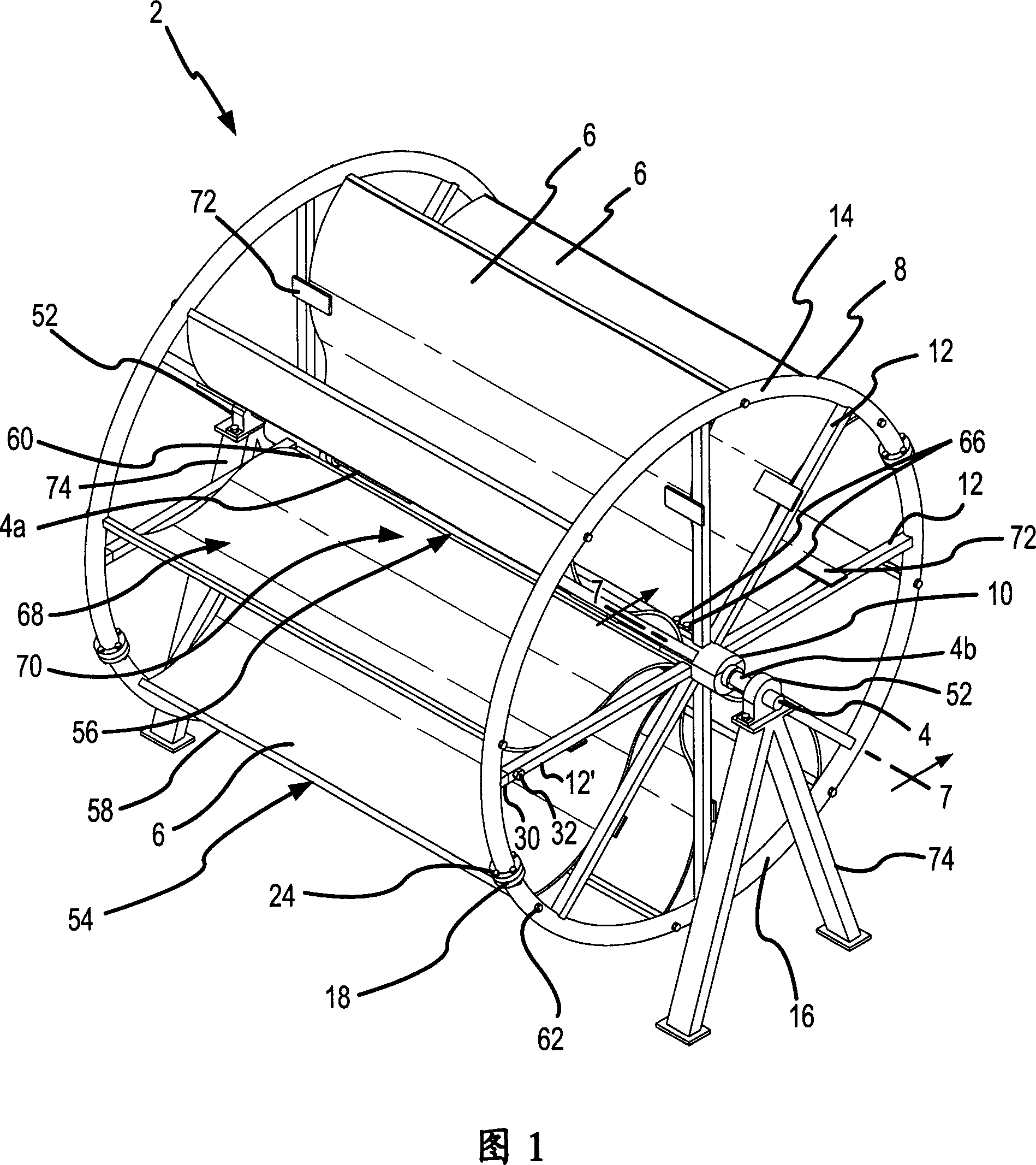
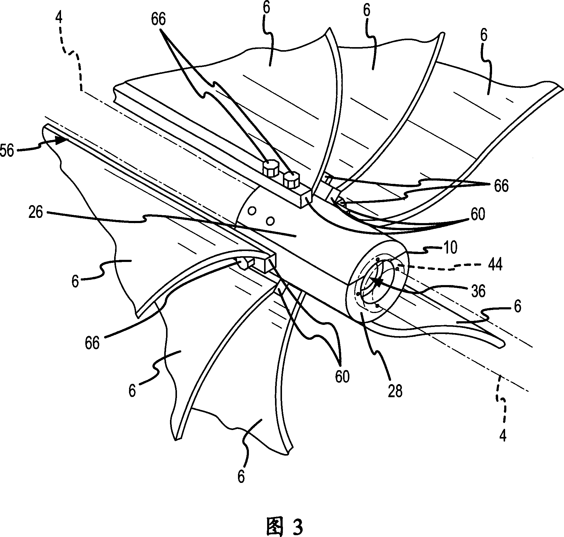
[0025] Here, the present invention discloses a novel wind-driven turbine system for generating electrical energy. The present invention presents a novel turbine design and generator connection as opposed to the propeller-style turbine designs that currently dominate the wind power industry. Each turbine has a plurality of S-shaped blades mounted parallel to and extending radially outward from the horizontally oriented axis. Each turbine shaft can be connected directly to the generator rotor, without a transmission, to generate electricity. The invention may comprise a row of such wind driven turbines mounted on a platform at the top of the tower.

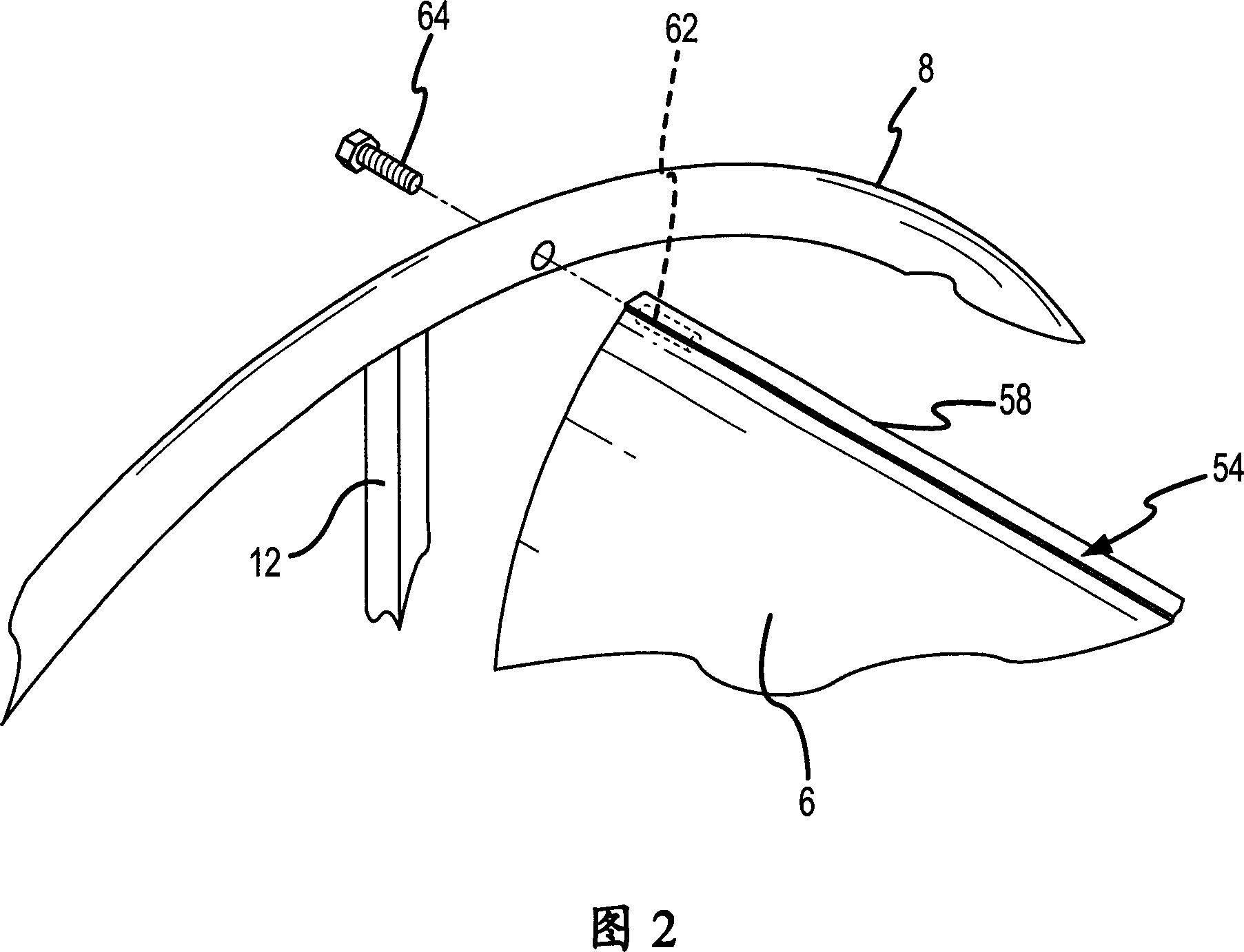
[0026] Figure 1 shows a turbine 2 used in a wind driven turbine system according to one embodiment of the invention. The main components of the turbine 2 include a shaft 4, a plurality of blades 6, a pair of rims 8 at opposite ends of the blades 6, a pair of axles 10 at the center of each rim, and in each rim 8 a corresponding bla...


PUM


Abstract

A wind driven turbine (2) has a plurality of sigmoid blades (6) with the trailing edge (56) of each blade (6) mounted parallel to a horizontally oriented shaft (4). Each blade (6) extends radially outward from the shaft (4). An electric generation system is composed of an array of the turbines (2) mounted on a platform (54) positioned on top of a tower (86). Each turbine shaft (4) may be connected directly with a generator (78) for producing electricity.

Description

[0001] Cross References to Related Applications [0002] This application claims priority to US Provisional Patent Application Serial No. 60 / 568,053, filed May 3, 2004, the entire contents of which are hereby incorporated by reference. technical field [0003] The invention relates to a wind-driven turbine for generating electrical energy. Background technique [0004] Wind has been used as an energy source to generate electricity for centuries. The first windmill was developed to automate the work of crushing grain and pumping water. The earliest known design of wind turbines was the vertical axis windmill developed in Persia around AD 500-900. Persian windmills were designed with vertical wings of reed bundles or timber connected by horizontal struts to a central vertical shaft. To grind the grain, millstones are fixed on vertical shafts. The grinding machine is usually enclosed in a building constructed with walls or shields to block the incoming wind from slowing dow...

Claims


Application Information

Patent Timeline
Patent Type & Authority Applications(China)
IPC IPC(8): F03D3/02F03D7/06F03D11/04F03B15/06F03D3/00F03D3/06
CPCF03D3/002F03D3/06Y02E10/74F03D3/02F03D7/06
Inventor 阿德姆·D·杜科维奇巴尔钱德拉·S·潘迪亚托米斯拉夫·斯特凡诺维奇马文·A·温格
Owner WIND ENERGY GRP INC
Why Eureka
Try Eureka