
Force-Based Heart Valve Sizing

A heart valve and sizer technology, applied in heart valves, medical science, surgery, etc., can solve unavoidable problems such as paravalvular, leakage and embolism risks

Active Publication Date: 2017-03-22
EDWARDS LIFESCIENCES CORP
View PDF10 Cites 0 Cited by
  • Summary
  • Abstract
  • Description
  • Claims
  • Application Information

AI Technical Summary

Problems solved by technology

However, sometimes newer valves have only three sutures or in some cases no sutures, making sizing accuracy more challenging
More difficult to avoid paravalvular leak and embolism risk if used three times or without sutures and sizing errors

Method used


Image

  • Force-Based Heart Valve Sizing
  • Force-Based Heart Valve Sizing
  • Force-Based Heart Valve Sizing

Examples


Embodiment Construction

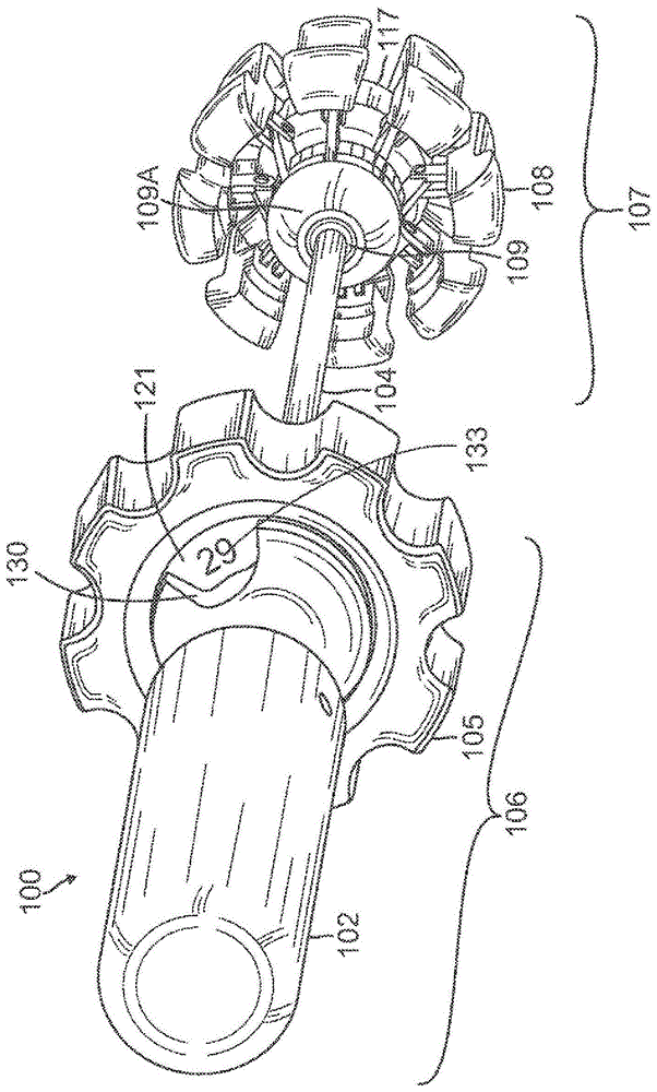
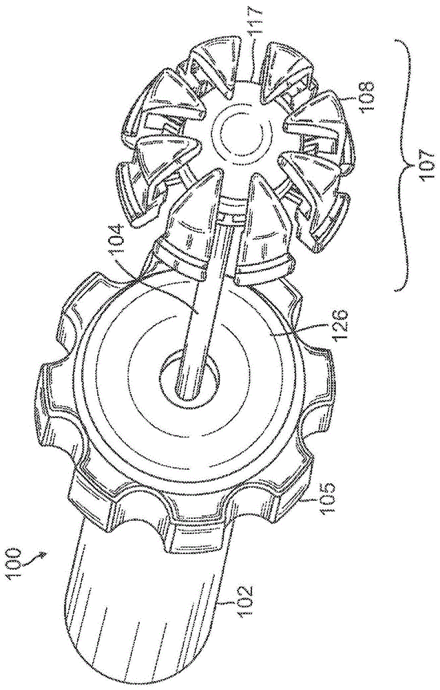
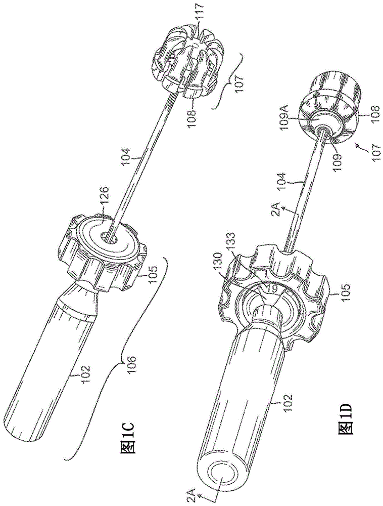
[0054] refer to Figure 1A - ID, shows the first valve sizer 100 . Valve sizer 100 includes an elongated hollow shaft 104 extending along the length of the sizer. An actuator assembly 106 is coupled to the proximal end of the shaft 104, while a radially expandable sizing element 107 is coupled to the distal end. The shaft 104 is preferably malleable to ensure that it is flexible enough to allow the sizer 100 to enter the annulus from different angles or through curved or curved access pathways. The handle 102 is preferably stationary and serves to hold the valve sizer steady in the operator's hand.

[0055] Referring to FIGS. 1C and 2A-2C , actuator assembly 106 includes actuator 105 , handle 102 , clutch ring 121 (also referred to as ring 121 ), and clutch cover 126 mounted in actuator 105 . The handle 102 threadingly engages a tubular threaded portion 121B which terminates axially upwardly from a ring 121 which in turn is mounted on the shaft 104 . Rotation of clutch ring...


PUM


Abstract

The present invention provides a valve sizer for determining the proper size of a replacement valve during valve replacement surgery. In one variation, the valve sizer has a hollow shaft with proximal and distal ends. A movable sizing element is coupled to the distal end of the shaft and is radially expandable between a first contracted and a second expanded position. The actuator assembly on the handle includes an actuator coupled to a clutch member via a ball-spring-detent clutch. A rod extends through the shaft and maintains a fixed distance between the handle and the distal hub in the sizing element. Movement of the actuator causes axial movement of the shaft, thereby causing radial expansion of the sizing leaflets relative to the hub. The clutch slips when the leaflets meet a predetermined reaction force from the surrounding valve annulus.

Description

[0001] related application [0002] This application claims priority under 35 U.S.C. §119 to U.S. Provisional Patent Application Serial No. 61 / 568,913, filed December 9, 2011. technical field [0003] The present disclosure relates to methods and apparatus for determining valve annulus size. More specifically, the present disclosure relates to heart valve sizers. Background technique [0004] Replacement of a diseased or malfunctioning heart valve requires accurate sizing of the valve annulus. After a diseased or malfunctioning heart valve has been removed, the surgeon measures the patient's valve annulus to determine the proper replacement valve size. [0005] Conventional systems for measuring a patient's valve annulus include multiple discs of varying sizes that can be removably or fixedly attached to a rod. The size of each disc corresponds to the available valve size. The surgeon inserts the disc into the patient's valve annulus and checks the fit of the disc in the...

Claims


Application Information

Patent Timeline
Patent Type & Authority Patents(China)
IPC IPC(8): A61F2/76A61F2/24A61M39/22
CPCA61F2/2496A61F2250/0073A61B2090/064A61B2090/065A61B2090/066A61B5/1076A61F2/243A61B2090/068
Inventor B·S·康克林
Owner EDWARDS LIFESCIENCES CORP
Learn More