Refrigerator
A technology for refrigerators and freezers, applied in the field of refrigerators, can solve problems such as easy dumping
- Summary
- Abstract
- Description
- Claims
- Application Information
AI Technical Summary
Problems solved by technology
Method used
Image
Examples
no. 1 approach
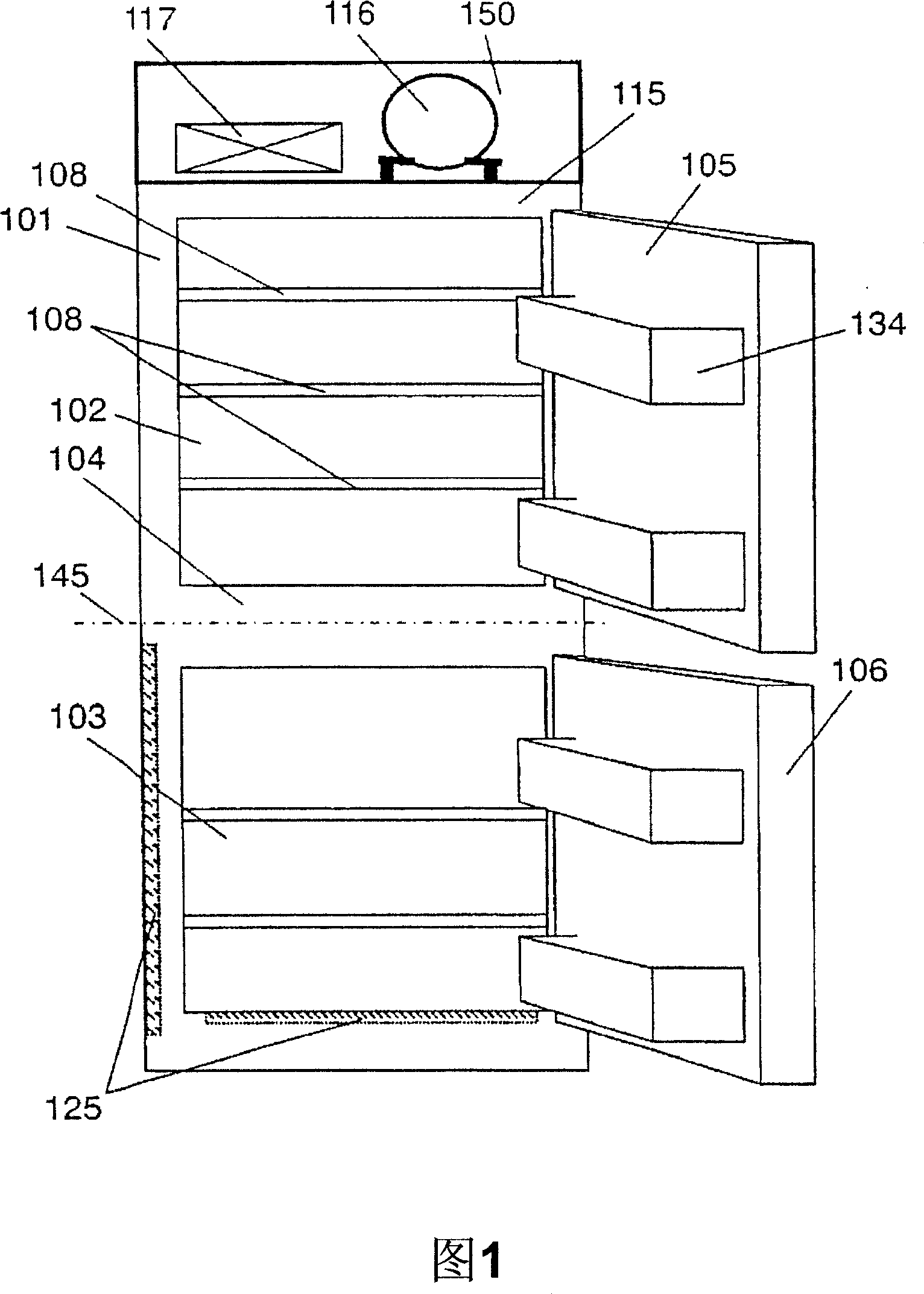
[0032] Fig. 1 is a schematic front view showing a refrigerator according to a first embodiment of the present invention. In FIG. 1 , the heat insulation box 101 is divided into two heat insulation sections, the upper part and the lower part are revolving door structures, wherein the upper part is a refrigerating room 102 and the lower part is a freezing room 103 . Insulation doors are respectively provided in each heat insulation section, and from above are the refrigerator compartment revolving door 105 and the freezer compartment revolving door 106 . A door built-in shelf 134 is provided on the revolving door 105 of the refrigerator as a storage space, and a plurality of storage shelves 108 are provided in the refrigerator.
[0033] In the refrigerating cycle, a compressor 116 and a condenser 117 arranged on the upper part 150 of the top surface, a capillary (not shown) as a decompressor (not shown), and an evaporator ( not shown in the figure).
[0034] Here, the lower en...
no. 2 approach
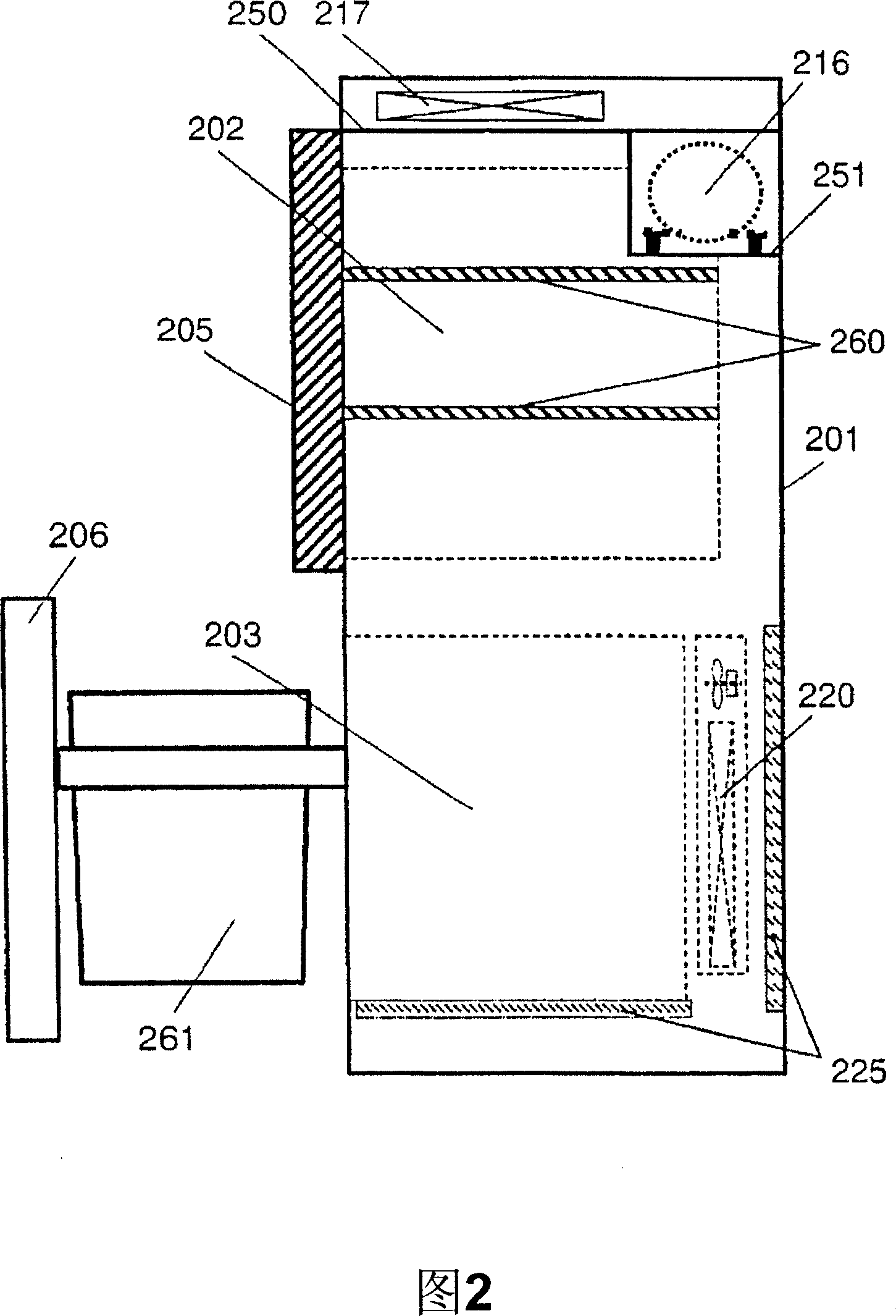
[0040] Fig. 2 is a schematic cross-sectional view showing a refrigerator according to a second embodiment of the present invention. In FIG. 2 , the heat insulation box body 201 is divided into two heat insulation sections, and the upper part has a revolving door, while the lower part has a drawer door structure, wherein the upper part is a refrigerator compartment 202 and the lower part is a freezer compartment 203 . Insulation doors are respectively provided in each heat insulation section, and from above are the revolving door 205 of the refrigerator compartment and the drawer door 206 of the freezer compartment. A refrigerator compartment shelf 260 and a freezer compartment storage box 261 are respectively provided on the refrigerator compartment revolving door 205 and the freezer compartment drawer door 206 as storage spaces.
[0041] The refrigerating cycle is a condenser 217 arranged on the first top 250, a compressor 216 arranged behind the refrigerator on the first top...
no. 3 approach
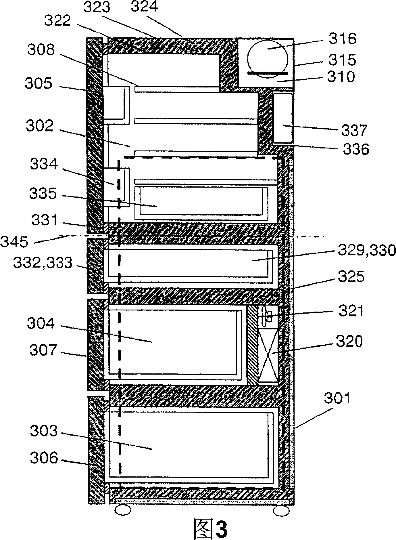
[0046] Fig. 3 is a schematic cross-sectional view showing a refrigerator according to a third embodiment of the present invention. 4 is a cross-sectional view showing a vacuum heat insulating material, FIG. 5 is a plan development view showing the refrigerator except for the front door, and FIG. 6 is a schematic cross-sectional view showing the refrigerator when it is tilted.
[0047] In FIG. 3 , the heat insulation box 301 has a heat insulation wall formed by vacuum forming an inner box 322 made of a resin such as ABS and an outer box 323 made of a metal material such as a pre-coated steel plate. The foam insulation body 324 is injected into the space to form. For the heat insulating foam body 324, for example, hard urethane foam, phenol foam, styrene foam, etc. can be used. As a foaming material, use of cyclopentane, a hydrocarbon, contributes more to avoiding the problem of global warming.
[0048] Moreover, in the space comprised by the inner case 322 and the outer case ...
PUM
 Abstract
Description
Claims
Application Information
 - R&D
- Intellectual Property
- Life Sciences
- Materials
- Tech Scout
- Unparalleled Data Quality
- Higher Quality Content
- 60% Fewer Hallucinations
Browse by: Latest US Patents, China's latest patents, Technical Efficacy Thesaurus, Application Domain, Technology Topic, Popular Technical Reports.
© 2025 PatSnap. All rights reserved.Legal|Privacy policy|Modern Slavery Act Transparency Statement|Sitemap|About US| Contact US: help@patsnap.com


