Electro-hydraulic manifold assembly with mounted pressure sensors

A technology for manifolds and assemblies, applied in the field of manifold assemblies, can solve the problems of increasing assembly complexity, size and cost

Inactive Publication Date: 2007-04-25
EATON CORP
View PDF2 Cites 8 Cited by
  • Summary
  • Abstract
  • Description
  • Claims
  • Application Information

AI Technical Summary

Problems solved by technology

[0004] However, having a pressure sensor at the outlet of each solenoid valve to generate an electrical signal indicative of the shift clutch actuation pressure adds to the complexity, size and cost of the assembly because this configuration requires multiple sensors and connections on the manifold. The various electrical leads of the solenoid valve

Method used


Image

  • Electro-hydraulic manifold assembly with mounted pressure sensors
  • Electro-hydraulic manifold assembly with mounted pressure sensors
  • Electro-hydraulic manifold assembly with mounted pressure sensors

Examples


Embodiment Construction

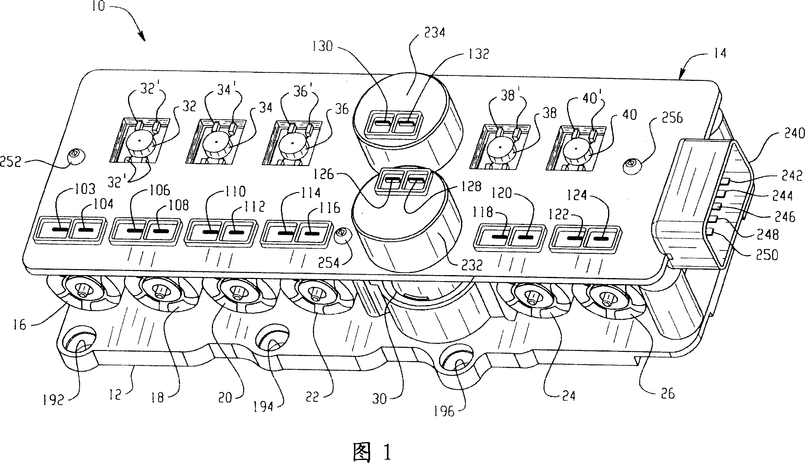
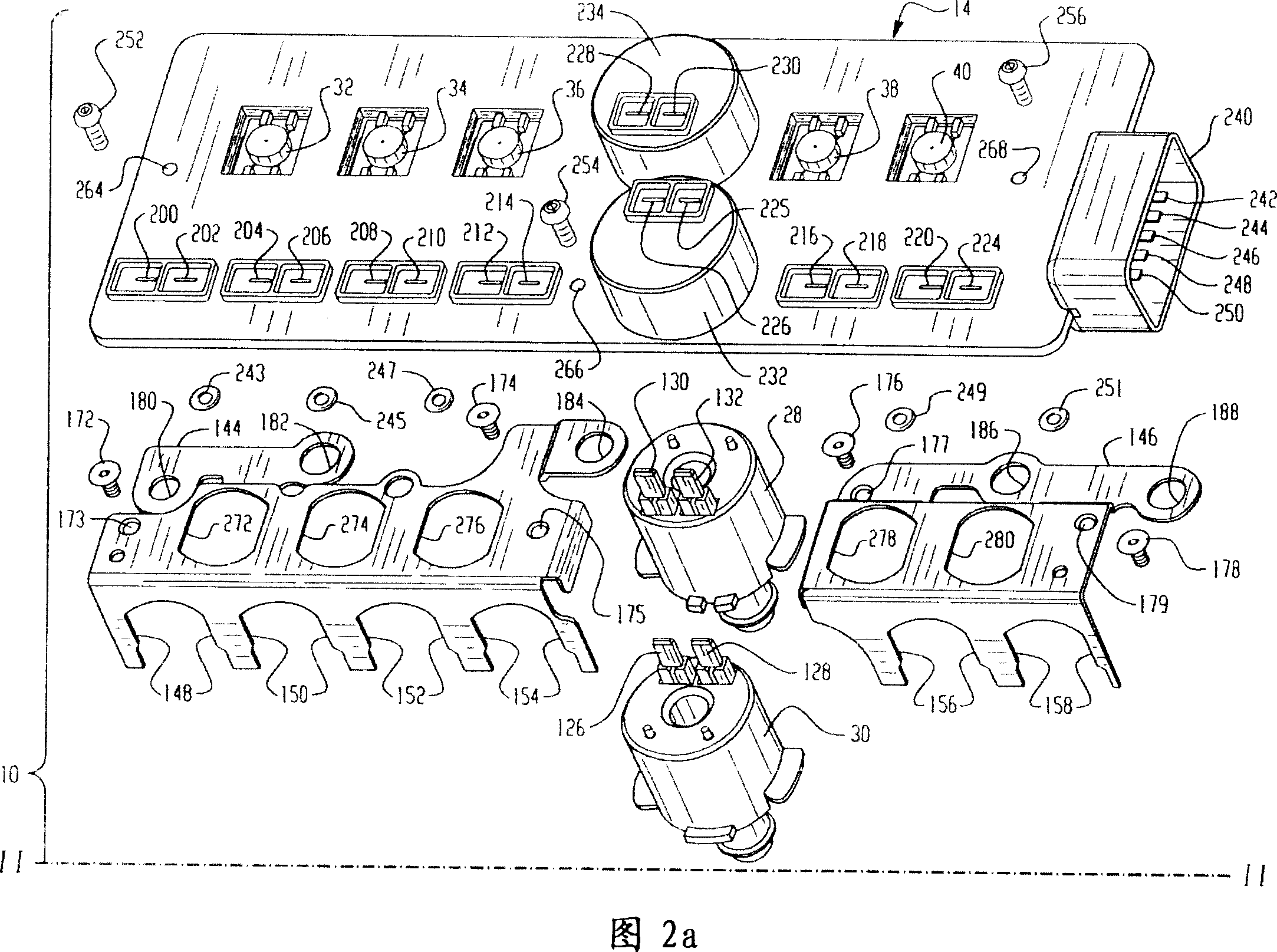
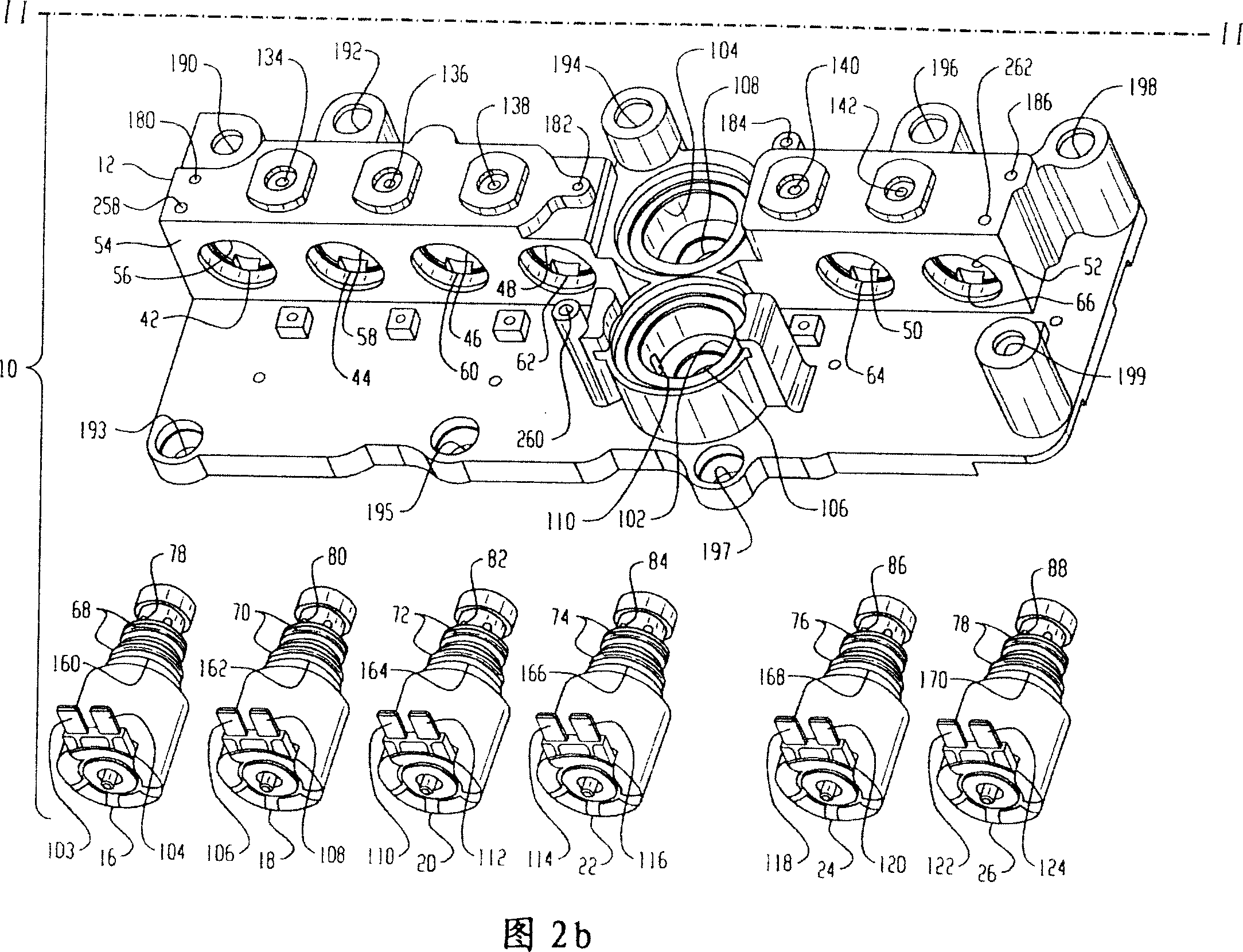
[0017] 1 to 5, one embodiment of the present invention is indicated generally at 10 and includes a manifold body 12, an electrical interface generally indicated at 14 and a plurality of solenoid valves 16, 18, 20, 22, 24, 26, 28, 30. Although these figures show a lead frame as the interface 14, the interface 14 can be any structure that distributes communication signals and power, such as fiber optic cables, plated traces, flex circuits, wiring, wireless interfaces, etc., as will be described below. Explain in more detail.

[0018] Interface 14 includes a plurality of pressure transducers or transducers 32, 34, 36, 38, 40, each having leads secured or connected to conductive strips indicated by primed transducer reference numerals respectively .

[0019] The manifold body 12 has a plurality of valve chambers 42, 44, 46, 48, 50, 52 formed horizontally in a vertically extending side 54 of the manifold body 12, each valve chamber having a valve chamber 56, 58, 60, 62, 64, 66 r...


PUM


Abstract

An electro-hydraulic manifold assembly with a plurality of solenoid operated valves disposed on a manifold block and each operable to control pressure from the inlet to a separate outlet. Sensing ports are provided in each outlet with a pressure sensor sealed over the sensing port for providing a signal indicative of the sensed pressure. The pressure sensors are mounted on a lead frame and connected to conductive strips in the lead frame. The lead frame has slots therein which permit the frame to be simultaneously electrically connected by bayonet connection to the terminals on each solenoid valve as the transducers are sealed over the sensing ports and the lead frame attached to the manifold block.

Description

[0001] This application is a continuation-in-part of application USSN 10 / 401408, filed March 28, 2003, which is now US Patent No. 6,929,031. technical field [0002] The present invention relates to manifold assemblies of the type having a hydraulic fluid pressure inlet in communication with a plurality of valve chambers each having a solenoid valve ported therein which when energized controls the selectivity Fluid pressure to a single outlet of the corresponding valve chamber. This type of manifold is used to control hydraulic fluid pressure in servo-actuated mechanisms such as clutch actuators for automatic power transmissions of motor vehicles where it is desired to control the transmission's speed changes or shift patterns with an electronic controller. This setup has found widespread use in modern vehicle automatic transmissions because the electronic controller is able to receive multiple inputs of vehicle operating parameters such as road speed, throttle position and en...

Claims


Application Information

Patent Timeline
Patent Type & Authority Applications(China)
IPC IPC(8): F16K11/24F15B13/00
Inventor G·E·福特T·J·格林D·E·赫伯特H·L·褒曼P·M·雅各布森M·L·戴里弗
Owner EATON CORP
Why Eureka
Try Eureka