Al technical title is built by PatSnap Al team. It summarizes the technical point description of the patent document.
A detector and laser technology, applied in the field of laser detectors, can solve problems such as low precision and slow speed, and achieve the effect of slow speed, fast speed and high economic benefits
Inactive Publication Date: 2007-04-25
SHENZHEN SHENLAN PRECISION MACHINERY
View PDF0 Cites 20 Cited by
Summary
Abstract
Description
Claims
Application Information
AI Technical Summary
This helps you quickly interpret patents by identifying the three key elements:
Problems solved by technology
Method used
Benefits of technology
Problems solved by technology
[0002] With the continuous development of the electronics industry, the demand for PCB boards has also increased accordingly. Therefore, the number of PCB micro-drill manufacturers has continued to increase, and the demand for various micro-drill testing equipment has continued to increase. However, the traditional manual detection method is slow. The accuracy is not high, and the laser detection instrument in this respect is still blank
Method used
Image
Click on the blue label to locate the original text in one second.
Reading with bidirectional positioning of images and text.
Examples
Embodiment Construction
[0041] The present invention can be used for the detection of various shafts. In this specific embodiment, a PCB micro-drill detector is taken as an example for illustration.
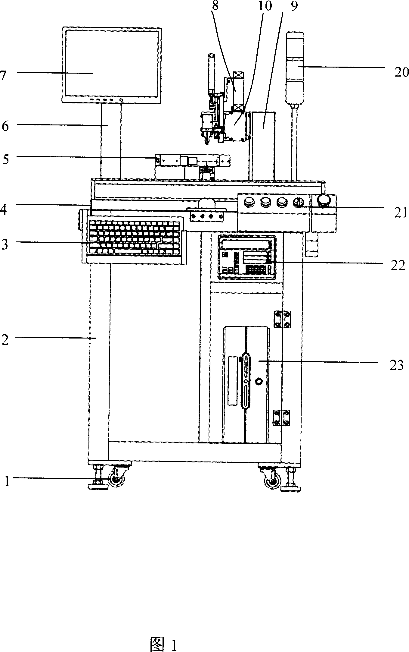
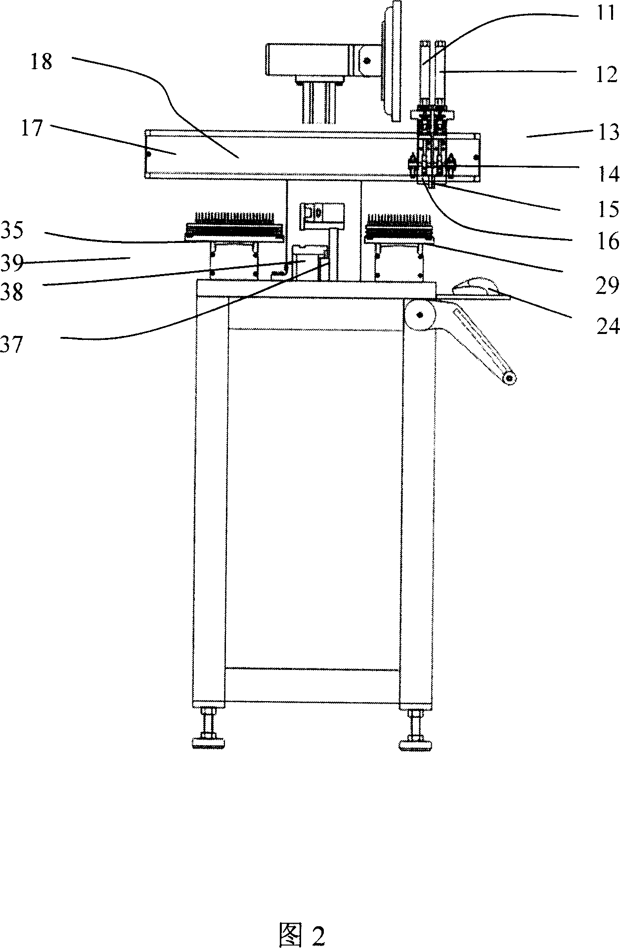
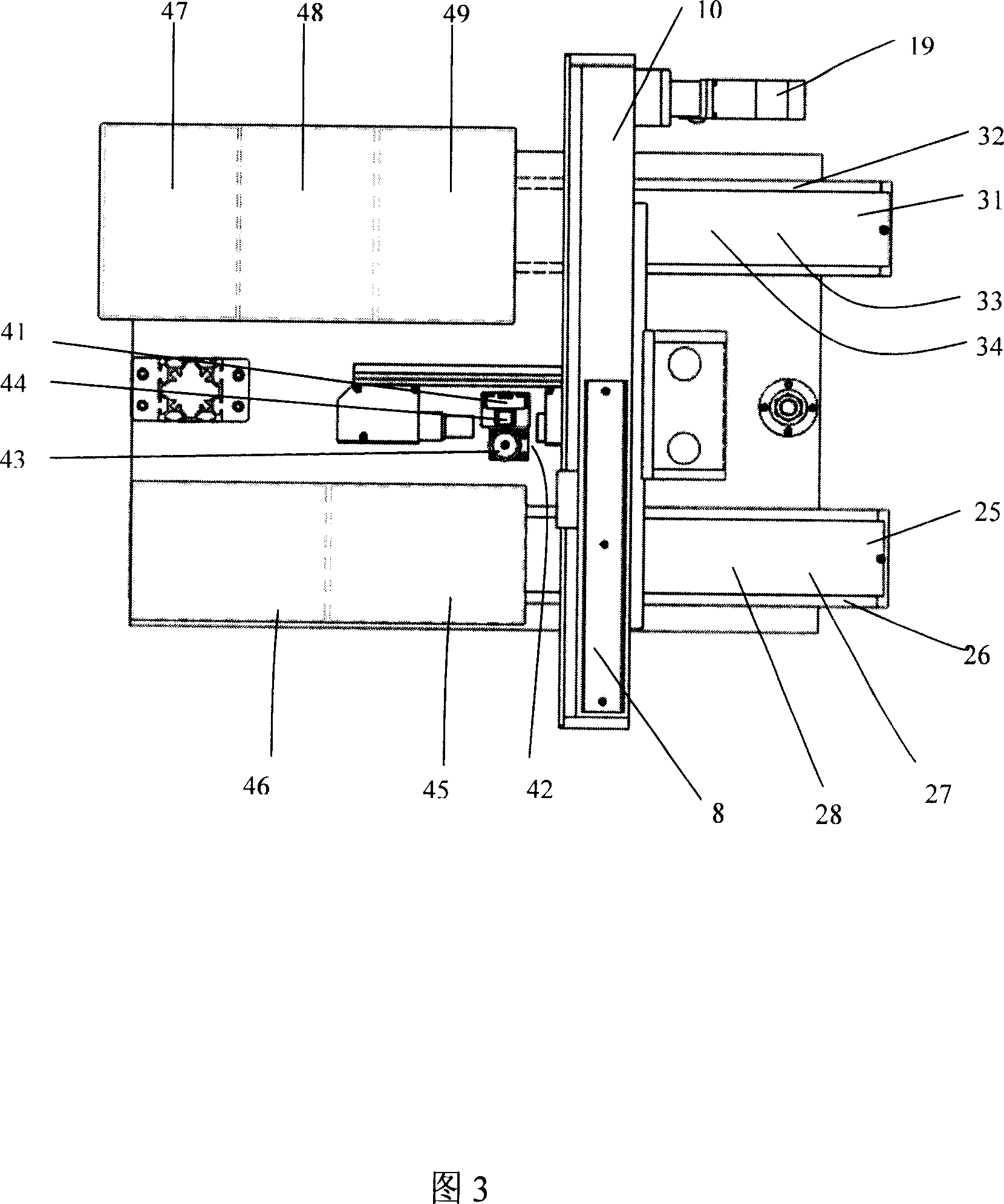
[0042] As shown in Fig. 1, Fig. 2, and Fig. 3, the laser microdrilling detector of the present embodiment is supported by the parts of the whole detection part and the whole control electric box by the body 2, and is arranged on the ground, by 4 casters and 4 feet cup 1 support; body 2 upper support plate 4 is provided with: a manipulator 8 that can slide freely on the main support plate 4 of the detection part, X1 axial feeding mechanism 25, X2 axial receiving mechanism 31, along the Z axis The non-contact laser head 5 that moves vertically and the display test data and the display 7 that is located on the display support frame 6 to display the software judgment result, the alarm indicator light 20 and the detection fixture when there is no material or abnormality.
[0043] In addition, the keyboard 3 ...
PUM
Abstract
A laser detecting instrument is disclosed that comprises body, laser head, mechanical arm, delivery device, material receiving device, detecting clamping fixture, laser controller. Said laser head is mounted on the laser lifting device which can make the laser head move along the direction of the Z axis, the laser lifting device is mounted on the body supporting plate, the delivery device, the material receiving device and the detecting clamping fixture are also mounted on the body supporting plate, the mechanical arm includes the mechanical fingers, the Y axis supporting device, the Z axis supporting device, and the mechanical fingers mounted on the Y axis supporting device which makes the mechanical fingers move along the direction of the Y axis, the Y axis supporting device is mounted on the Z axis supporting device which is mounted on the body supporting plate to support the whole mechanical arm. The laser detecting instrument includes the control device which controls the movement of said laser head, the laser controller, the mechanical arm, the delivery device, the material receiving device, the detecting clamping fixture. The invention has high precision in detection, fast speed, flexible setting for parameters, simple and convenient operation, and it has the large market and good economic benefit.
Description
technical field [0001] The invention relates to a laser detector, in particular to a laser detector used for detecting the outer diameter and shape tolerance of shafts. Background technique [0002] With the continuous development of the electronics industry, the demand for PCB boards has also increased accordingly. Therefore, the number of PCB micro-drill manufacturers has continued to increase, and the demand for various micro-drill testing equipment has continued to increase. However, the traditional manual detection method is slow. The accuracy is not high, and the laser detection instrument in this respect is still blank. Contents of the invention [0003] The problem to be solved by the present invention is to provide a fast, accurate and multi-functional laser detector for detecting PCB micro-drilling semi-finished products and finished products. [0004] The laser detector of the present invention includes a body, a laser head, a manipulator, a feeding mechanism, ...
Claims
Application Information
Patent Timeline
Application Date:The date an application was filed.
Publication Date:The date a patent or application was officially published.
First Publication Date:The earliest publication date of a patent with the same application number.
Issue Date:Publication date of the patent grant document.
PCT Entry Date:The Entry date of PCT National Phase.
Estimated Expiry Date:The statutory expiry date of a patent right according to the Patent Law, and it is the longest term of protection that the patent right can achieve without the termination of the patent right due to other reasons(Term extension factor has been taken into account ).
Invalid Date:Actual expiry date is based on effective date or publication date of legal transaction data of invalid patent.