Bridging type fault injection apparatus and method of fault-tolerant computer system

A fault-tolerant computer, fault injection technology, applied in the detection of faulty computer hardware, the generation of response errors, instruments, etc., can solve the problems of inability to monitor system status, lack of versatility, inconvenient connection of injection points, etc., to avoid inconvenience , The effect of simplifying the process of fault injection

Inactive Publication Date: 2007-04-25
HARBIN INST OF TECH
View PDF0 Cites 19 Cited by
  • Summary
  • Abstract
  • Description
  • Claims
  • Application Information

AI Technical Summary

Problems solved by technology

[0006] The object of the present invention is to provide a fault-tolerant computer system that can completely solve the four major problems of existing fault injection: lack of versatility, inconvenient connection of injection points, inability to synchronize with the target system, and inability to monitor system status Type fault injection device and method

Method used


Image

  • Bridging type fault injection apparatus and method of fault-tolerant computer system
  • Bridging type fault injection apparatus and method of fault-tolerant computer system
  • Bridging type fault injection apparatus and method of fault-tolerant computer system

Examples


specific Embodiment approach 1

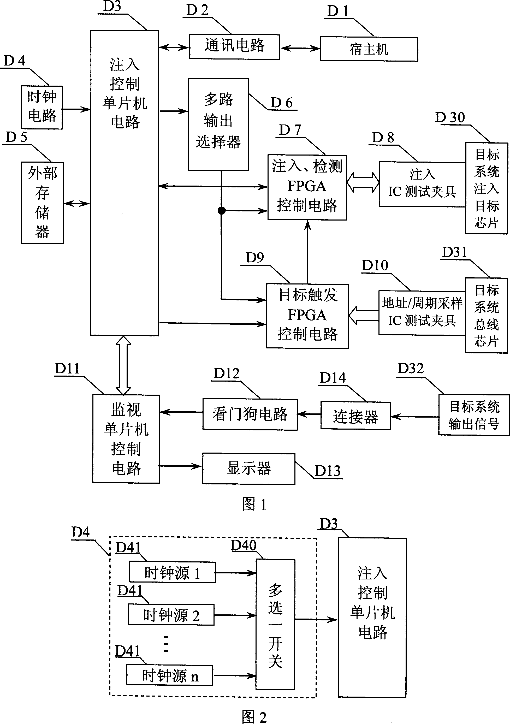
[0026] Specific embodiment one: see Fig. 1 , Fig. 3 to Fig. 10 . The overlapping fault injection device of the fault-tolerant computer system of the present embodiment is composed of host machine D1, communication circuit D2, injection control single-chip microcomputer circuit D3, clock circuit D4, external memory D5, multiplex output selector D6, injection / detection FPGA control circuit D7, injection IC test fixture D8, target trigger FPGA control circuit D9, address / period sampling IC test fixture D10, monitoring single-chip microcomputer control circuit D11, watchdog circuit D12 and connector D14.

[0027] The 232 serial communication port of the host computer D1 is connected with the 232 serial communication port of the communication circuit D2, and the TTL level input and output terminals of the communication circuit D2 are respectively connected with the serial output and input terminals of the injection control microcontroller circuit D3; the clock circuit The clock sig...

specific Embodiment approach 2

[0125] Specific embodiment two: referring to Fig. 2, the difference between the overlapping type fault injection device of the fault-tolerant computer system of the present embodiment and the specific embodiment one is that the clock circuit D4 is composed of several clock sources 41 of different frequencies and one of multiple choices The switch 40 is formed, the clock signal output ends of several different frequency clock sources 41 are respectively connected with a plurality of input ends of the multi-select one switch 40, and the output end of the multi-select one switch 40 is connected with the clock signal input end of the injection control single-chip microcomputer circuit D3 .

[0126] The clock circuit D4 in the lap-type fault injection device of the fault-tolerant computer system of the present embodiment can select the operating clock of injection control single-chip microcomputer 3 according to the situation of the fault injection target system, so that the lap-typ...

specific Embodiment approach 3

[0127] Specific embodiment three: referring to Fig. 1, on the basis of the specific embodiment one or two, the overlapping type fault injection device of the fault-tolerant computer system of the present embodiment has increased the display D13, and the control input end of the display D13 and the monitoring single-chip microcomputer control The output end of the circuit D11 is connected, and the display D13 of this embodiment is a four-digit nixie tube display.


PUM


Abstract

This invention relates to a error tolerant computer system hinge fault injection device and method, wherein the device adopts IC test clamper and injection aim system chip for hinge connection; the host machine is connected to injection control single machine circuit through communication circuit; the injection control single machine circuit is separately connected to multi-path output selector, injection or test FPGA control circuit, aim trigger FPGA control circuit and monitor control single machine circuit.

Description

technical field [0001] The invention relates to the technical field of fault injection of fault-tolerant computer systems. Background technique [0002] Computer systems used in the fields of aerospace, finance, post and telecommunications, etc. will inevitably be disturbed by various environments during their operation. If the system fails, it will cause serious consequences and heavy losses. In order to improve the reliability of the computer system and meet the requirements of long running time, it is usually necessary to include a fault-tolerant function, which puts forward higher requirements for the reliability of the fault-tolerant system itself, so that the system can still operate reliably when a fault occurs. malfunction occurs. [0003] It can be seen that the fault-tolerant technology used in the system must be tested and analyzed, so as to ensure that the designed fault-tolerant system can truly achieve the goal of correctly handling the predetermined faults. ...

Claims


Application Information

Patent Timeline
Patent Type & Authority Applications(China)
IPC IPC(8): G06F11/22G06F11/07G06F13/10
Inventor 杨孝宗刘宏伟吴智博左德承崔刚舒燕君董剑温东新苗百利向琳张展罗丹彦王玲
Owner HARBIN INST OF TECH
Why Eureka
Try Eureka