Circuit breaker

A circuit breaker and moving contact technology, applied in the direction of protection switch operation/release mechanism, etc., can solve the problems of grid plate setting space and configuration block number limitation, circuit breaker breaking performance impact, stop pin breakage and other problems

Inactive Publication Date: 2007-04-25
FUJI ELECTRIC ASSETS MANAGEMENT
View PDF1 Cites 2 Cited by
  • Summary
  • Abstract
  • Description
  • Claims
  • Application Information

AI Technical Summary

Problems solved by technology

Therefore, the impact load applied to the stopper pin from the movable contact is concentrated on the ridge line portion in contact with the movable contact, thereby breaking the stopper pin subjected to the excessive concentrated load.
In...

Method used


Image

  • Circuit breaker
  • Circuit breaker
  • Circuit breaker

Examples


no. 1 example

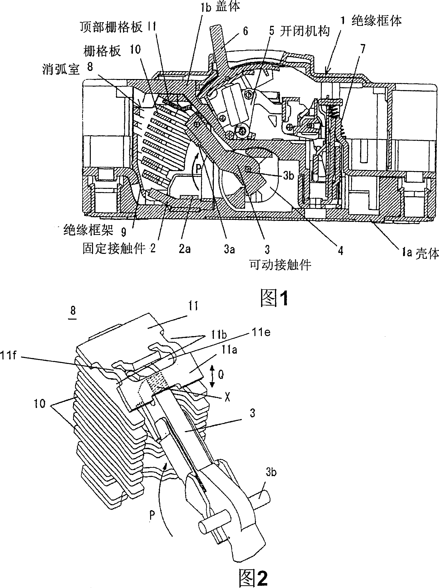
[0031] In Figs. 1 to 4, reference numeral 1 indicates the insulating frame (resin molded housing) of the circuit breaker composed of two separate structures of the housing 1a and the cover 1b, and the reference numeral 2 indicates the power supply side. The fixed contact piece of the main circuit terminal, the label 2a indicates the fixed contact, the label 3 indicates the rotary movable contact, the label 3a indicates the movable contact, and the label 3b indicates the rotation of the movable contact 3 The fulcrum, the symbol 4 represents the contact seat that holds the movable contact 3, the symbol 5 represents the toggle link type (togglering) opening and closing mechanism connected to the contact seat 4, and the symbol 6 represents the opening and closing mechanism. Close the operating handle, the number 7 indicates the thermal overcurrent drawing device, and the number 8 indicates the arc suppression chamber arranged in front of the movable contact 3 along the opening and ...

no. 2 example

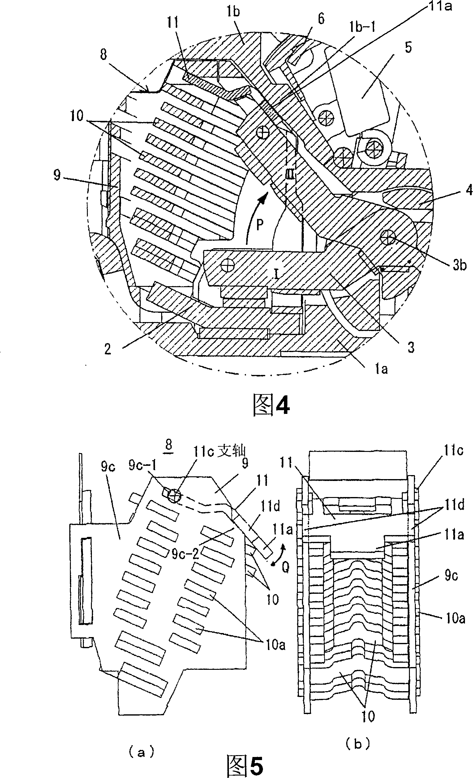
[0044] Next, an embodiment of the present invention will be described using Fig. 5(a) and (b). In this embodiment, for the top grid plate 11 held on the top of the insulating frame of the isolation chamber 8, a support shaft 11c protruding to the left and right sides is formed at the front end thereof, and a lateral support shaft 11c is formed at the rear side thereof. Engagement ears 11d whose edges protrude to the left and right sides. On the other hand, on the insulating frame side of the isolation chamber 8, on the top of the left and right side walls 9c, a bearing hole 9c-1 for inserting the above-mentioned support shaft 11c is formed through, and at the same time, the rear upper end surface of the side wall 9c is It is made as an inclined surface on which the ear portion 11d of the above-mentioned top grid plate 11 is sandwiched so that in this position, the collision portion 11a at the rear end protrudes from the back surface of the desolation chamber 8 . In addition, ...


PUM


Abstract

Provided is a circuit breaker, wherein a fixing contact piece, a rotation movable contact piece connected with the switch mechanism and an arc extinguish chamber are disposed on the interior of the frame which is consisted of a shell and a cover. The arc extinguish chamber is configured of a box-shaped insulating frame and a multilayer grid plates in the same which is arranged on the switch path of the movable contact piece, the top of the insulating frame is disposed to face and approach the inner surface of the cover, the collision component of the movable contact piece which limits the terminal position of the movable contact piece as a stop component, is arranged on the top grid plate of the arc extinguish chamber for extending, therefore, the top grid plate is movably stopped on the top of the insulating frame. The back of the movable contact piece is configured to contact with the collision component during the cutoff action, therefore dispersing the impact load on the top grid plate and the cover of the circuit breaker which stops the jumping displacement of the top grid plate, and stops the action of the movable contact piece on the cutoff-terminal position.

Description

technical field [0001] The present invention relates to, for example, a circuit breaker aimed at line circuit breakers, and more specifically, to a stopper for limiting the opening terminal position of a movable contact that is installed in an arc extinguishing chamber of a circuit breaker and is opened during a circuit breaking operation. The structure of the institution. Background technique [0002] As we all know, when an excessive current such as a short-circuit current flows in the main circuit, the line circuit breaker uses the electromagnetic repulsion force acting between its fixed contact and movable contact to drive the movable contact from the closed position to the disconnected position At the same time, an arc suppression chamber with a grid plate (anti-ion grid) is arranged on the opening and closing movement path of the movable contact, and the arc generated between the fixed contact and the movable contact is pressed into the arc suppression chamber , using...

Claims


Application Information

Patent Timeline
IPC IPC(8): H01H71/12
Inventor 山崎智雄佐藤朗史浅川浩司
Owner FUJI ELECTRIC ASSETS MANAGEMENT
Why Eureka
Try Eureka