Brake for towline of elevator

A rope brake, elevator traction technology, applied in the direction of the hoisting device, etc., can solve the problems of different force of the lock hook, uncertainty of the safety control of the lock hook, etc., to improve stability, overcome uncertain factors, and improve safety and reliability sexual effect

Active Publication Date: 2007-05-02
HANGZHOU HUNING ELEVATOR PARTS CO LTD
View PDF1 Cites 19 Cited by
  • Summary
  • Abstract
  • Description
  • Claims
  • Application Information

AI Technical Summary

Problems solved by technology

However, this trigger mechanism has disadvantages
Because the external force is affected by the speed of movement, the direction of action,

Method used


Image

  • Brake for towline of elevator
  • Brake for towline of elevator
  • Brake for towline of elevator

Examples


Example Embodiment

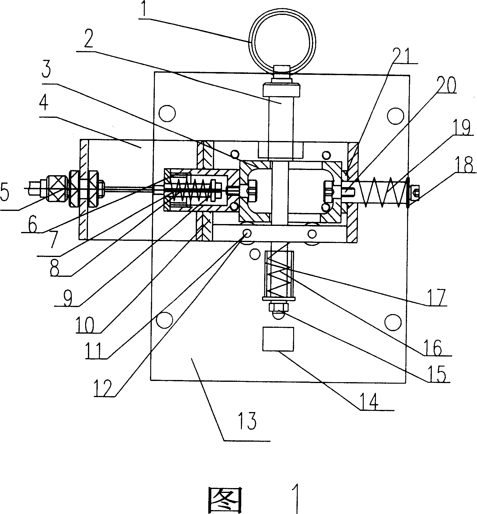
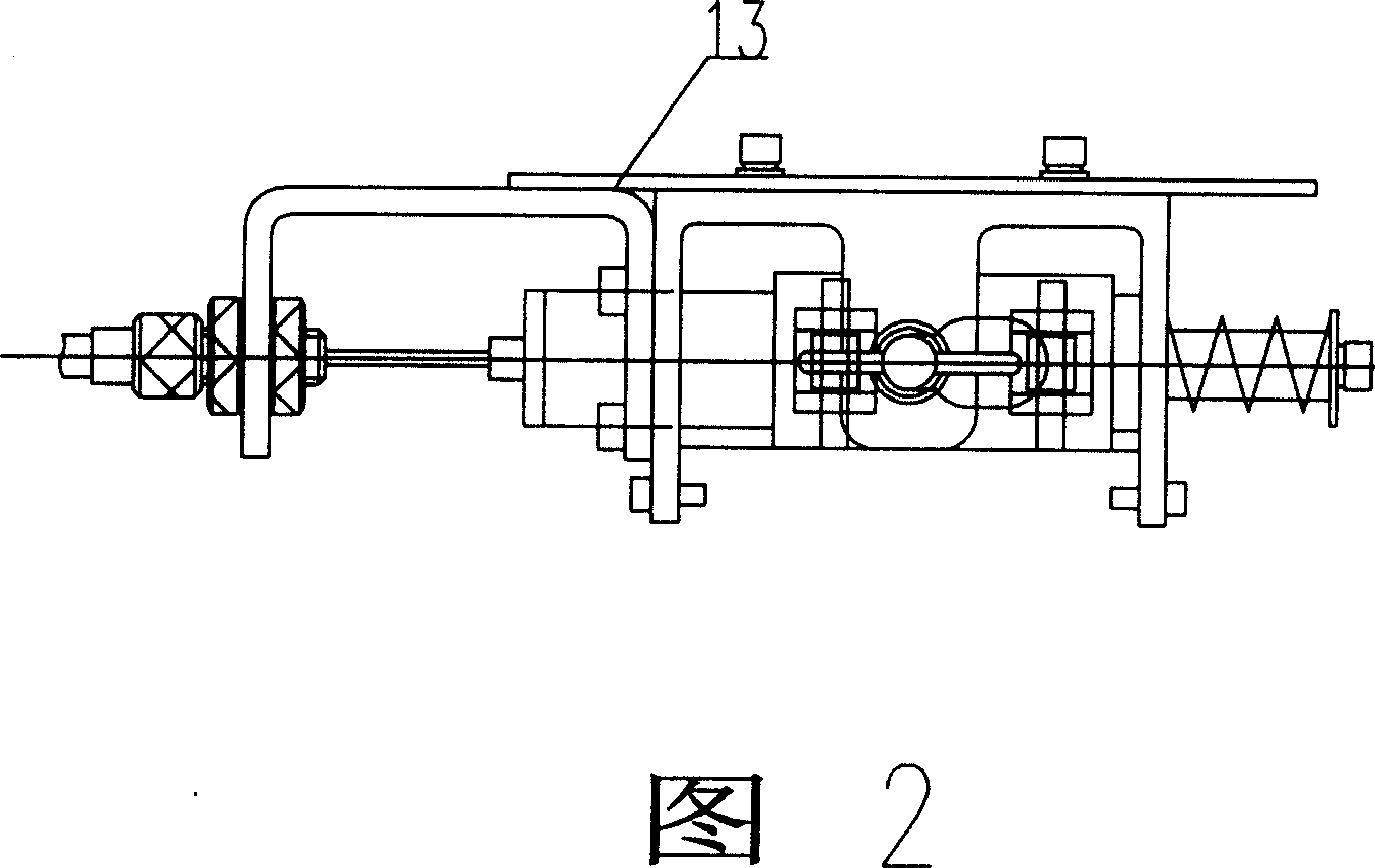
[0022] Embodiment 1: As shown in Figures 1, 2, and 5, the mechanical trigger mechanism is composed of an impact component 31, a brake wire component 32, a reset component 33, and a bearing component 12. The impact component 31 is pressed by an impact spring 16 in the bearing component 12 On the upper pull plate 3, the brake wire assembly 32 is fixedly connected to the pull plate 3 on the bearing assembly 12 by screws. The brake wire 5 is driven by an external force to pull the pull plate 3 to slide to one end, so that the impact assembly 31 loses support and moves downward. And under the action of the impact spring 16, the impact is realized, the reset component 33 is fixedly connected with the pull plate 3, and the pull plate 3 is pushed to reset by the return spring 19.

[0023] The impact assembly 31 is composed of a pull ring 1, a guide post 2, a spacer 8, an impact spring 16, and a top screw 15. The pull ring 1 is rotatably installed at one end of the guide post 2, and the gu...

Example Embodiment

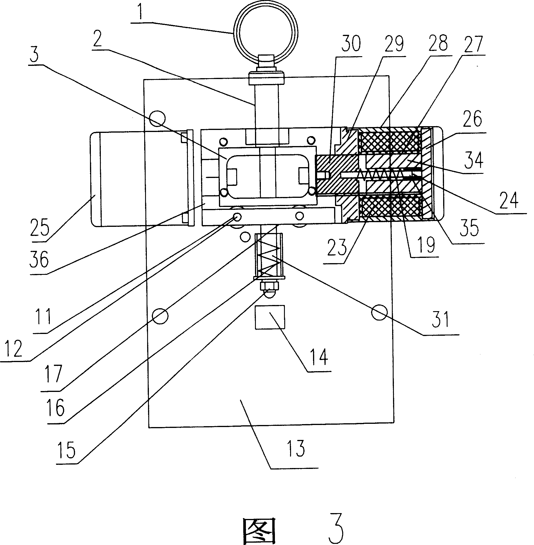
[0028] Embodiment 2: As shown in Figures 3, 4, and 6, the electromagnetic trigger mechanism is composed of an impact assembly 31, an electromagnet assembly 24, a wiring assembly 25 and a bearing assembly 12. The impact assembly 31 is compressed on the bearing assembly 12 by an impact spring. The pull plate 3 is supported by the pull plate 3. The armature 30 of the electromagnet assembly 24 is fixedly connected to the pull plate 3 by screws. When the electromagnet 34 is energized, electromagnetic force is generated, and the electromagnetic force moves the pull plate 3 to one end , Open the lock hook 14 to realize the impact.

[0029] The impact assembly 31 is composed of a pull ring 1, a guide post 2, a spacer sleeve 17, an impact spring 16, and a head screw 15. The pull ring 1 is rotatably installed at one end of the guide post 2, and the guide post 2 extends into the impact spring 16, and the spacer sleeve 17 is sleeved outside the impact spring 16, and the spacer 17 and the guid...


PUM


Abstract

A brake for the traction cable of elevator has a trigger mechanism, which is composed of an impact module, an electromagnetic module, a connecting string module, and a bearing module. The pull plate on bearing module is pressed by said impact module via impact spring. Said pull plate is connected with electromagnetic module and is moving toward one end under the action of electromagnetic module to implement impact. A restoring spring can restore the pull plate to original position.

Description

technical field [0001] The invention belongs to the manufacturing field of an elevator overspeed protection device, in particular to a trigger device for an elevator traction rope brake. Background technique [0002] The elevator traction rope brake provides a guarantee for the safe operation of the elevator. Chinese Patent No. 01274866.8 provides an elevator traction rope brake, which can effectively perform balanced braking and implement overspeed protection when the elevator goes up and down over speed. The trigger mechanism of this patent is composed of a lock hook frame, a lock hook and a coaxial brake wire. The trigger of the lock hook is a mechanical signal obtained from the two-way speed limiter through the coaxial brake wire. When the elevator car exceeds the speed, the speed limiter will act. Drive the coaxial brake line to pull the lock hook, release the sliding shaft to drive the brake lining to move, and then clamp the traction rope ...

Claims


Application Information

Patent Timeline
IPC IPC(8): B66D5/16
Inventor 邹家春
Owner HANGZHOU HUNING ELEVATOR PARTS CO LTD
Why Eureka
Try Eureka