Remote control system, and display device and electronic device using the remote control system

A technology of remote control system and electronic equipment, which is applied in the direction of remote measurement/remote control selection device, TV system components, selection device, etc., and can solve the problems of complex structure of remote control transmitter and complex signal processing of remote control transmitter, etc.

Inactive Publication Date: 2007-05-02
SHARP KK
View PDF4 Cites 30 Cited by
  • Summary
  • Abstract
  • Description
  • Claims
  • Application Information

AI Technical Summary

Problems solved by technology

Therefore, there is a problem that the structure of the remote control transmitter is complicated and the signal processing on the side of the remote control transmitter is also complicated.
The invention described in this patent document 2 can move the pointer by moving the transmitter of the remote controller, but the processing after the movement is still the key operation of the transmitter of the remote controller, and the complexity of the key operation

Method used


Image

  • Remote control system, and display device and electronic device using the remote control system
  • Remote control system, and display device and electronic device using the remote control system
  • Remote control system, and display device and electronic device using the remote control system

Examples


Embodiment approach 1

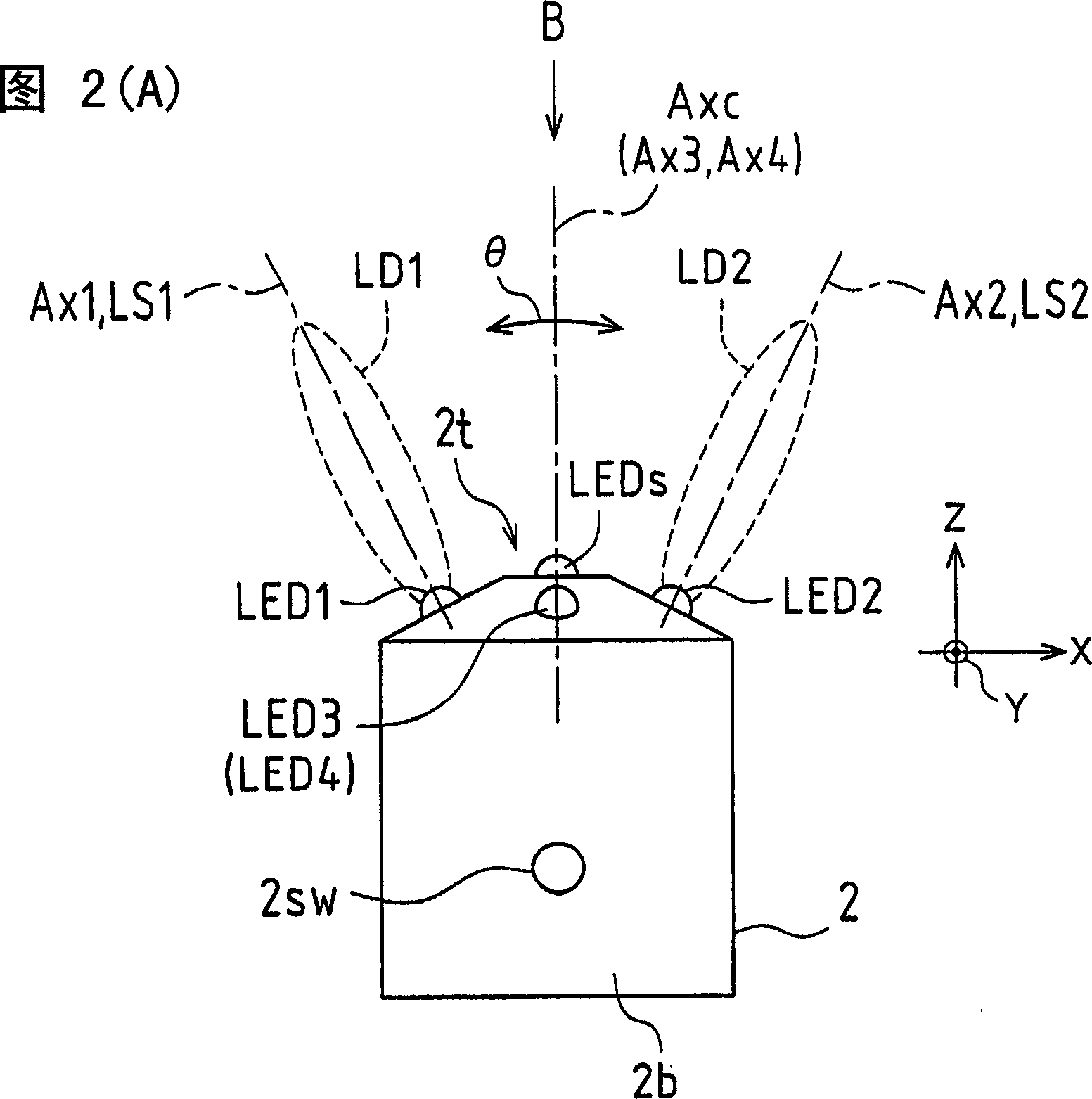
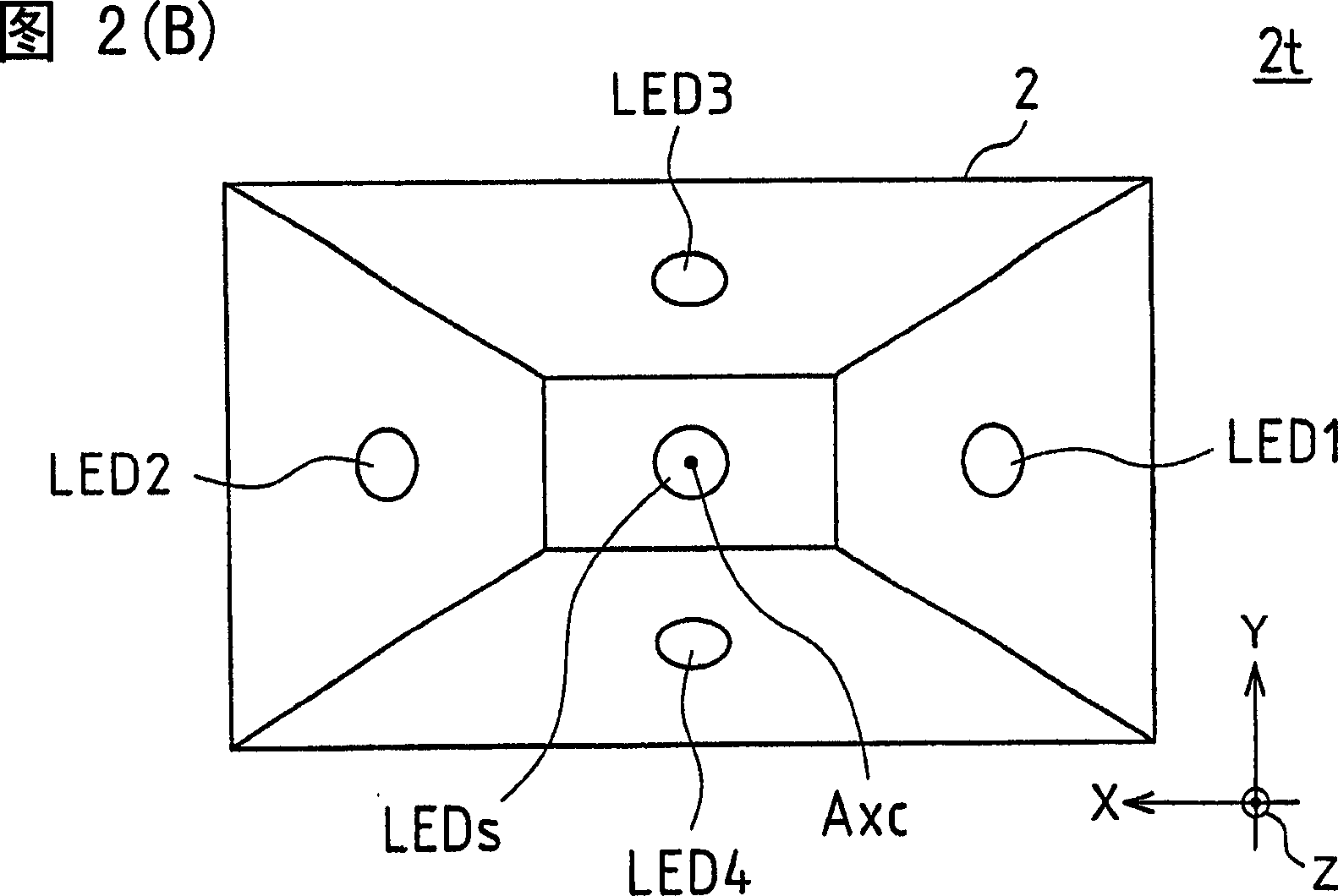
[0196] 2(A) and FIG. 2(B) are explanatory diagrams showing the outline of the appearance of the remote control transmitter according to Embodiment 1 of the present invention, and FIG. (B) is a front view seen from the arrow B direction of FIG. 2(A).

[0197] Taking the intersection of the central axis Axc of the transmitter 2 and the front end 2t of the transmitter 2 (the front of the transmitter 2 facing the photoreceptor 3p) in the first axis direction X (corresponding to the horizontal direction) as the center, the second The first light emitting element LED1 (arranged on the right side in the front view) and the second light emitting element LED2 (arranged on the left side in the front view) are symmetrically arranged on the front end portion 2t of the transmitter 2 .

[0198] The first light-emitting element LED1 and the second light-emitting element LED2 are disposed on the inclined surface appropriately formed on the tip portion 2t so as to form optical axes Ax1 and Ax2...

Embodiment approach 2

[0253] The specific displacement detection and the display state of the display screen in the remote control system 1 shown in the first embodiment will be described as the second embodiment. In this embodiment, for ease of understanding, a case where the transmitter 2 is moved (displaced, oscillated) only in the horizontal direction (first axial direction X) will be described. Therefore, although the movement in the vertical direction (second axis direction Y) will not be described, it can be applied in the same way. By appropriately combining the values ​​(amplitude ratio as the amplitude relative relationship, the logarithm of the amplitude ratio as the amplitude relative relationship) obtained by moving in the two directions of the horizontal direction and the vertical direction, two-dimensional The movement detection (displacement detection, swing detection) of the direction is omitted, so the description is omitted.

[0254] FIG. 8 is a diagram showing an arrangement of...

Embodiment approach 3

[0293]In this embodiment, the logarithm of the amplitude ratio shown in Embodiment 2 is further linearly approximated to detect the displacement of the transmitter 2 . That is, the amplitude relative relationship is taken as a linear approximation of the logarithm of the amplitude ratio.

[0294] 14 is a graph showing the relationship between the swing angle and the logarithm of the amplitude ratio of the position detection output signal when linear approximation is applied to the position detection output signal in the remote control system according to Embodiment 3 of the present invention.

[0295] The data in this embodiment are the same as those in Embodiment 2, and similar to FIG. 10 , the horizontal axis is taken as the swing angle θ (degrees), and the vertical axis is taken as the logarithm of the amplitude ratio log(VL1 / VL2). The system 1 (receiver 3) of this embodiment uses the logarithm of the amplitude ratio as an approximate straight line AL within the range of th...


PUM


Abstract

The present invention discloses a remote control system, and display device and electronic device using the remote control system. One embodiment of a remote control system according to the invention includes: a remote control transmitter including a light-emitting element control unit that emits light-emitting element that emit position detection light signals; a remote control receiver including a light-reception signal processing unit that detects position detection reception signals from the position detection light signals, an output detection unit that performs waveform conversion on the position detection reception signals to obtain output signals as position detection output signals, and an arithmetic processing unit that calculates a displacement of the remote control transmitter in a first axis direction and a second axis direction based on an amplitude correlation of output signals; and a cursor control unit that controls the position of the cursor based on the displacement of the remote control transmitter in the first axis direction and the displacement of the remote control transmitter in the second axis direction.

Description

[0001] This application claims priority based on Patent Application No. 2005-295132 filed in Japan on October 7, 2005 and Patent Application No. 2005-327610 filed in Japan on November 11, 2005. Its entire contents are incorporated into this application by reference thereto. technical field [0002] The present invention relates to a remote control system for remotely controlling the position of a cursor displayed on a display screen and a display device for controlling the cursor displayed on a display screen using the remote control system, and to a television receiver with a remote control operation device (remote control transmitter) , program video recorders, game consoles, TV telephone systems, anti-risk cameras and other electronic equipment. Background technique [0003] Conventionally, there is known a remote control device for remotely operating a cursor displayed on a display surface of a display device. As a remote control device, for example, in the case of a pe...

Claims


Application Information

Patent Timeline
IPC IPC(8): G06F3/033G06F3/044G06F3/023G06F3/048H04N5/445G06F3/0346G06F3/0481G06F3/0486G06F13/00H04N5/00H04Q9/00
Inventor 青木文彦久川浩司
Owner SHARP KK
Why Eureka
Try Eureka