Centrifugally activated bobbin coupling

A coupling and bobbin technology, applied in textiles and papermaking, etc., can solve the problems of damage, wear, high cost of manufacturing and assembly, and achieve the effects of easy manufacturing, low cost, and strong wear and tear.

Inactive Publication Date: 2010-05-05
TEXPARTS GMBH
View PDF7 Cites 0 Cited by
  • Summary
  • Abstract
  • Description
  • Claims
  • Application Information

AI Technical Summary

Problems solved by technology

Relatively expensive to manufacture and assemble
The edge of the cylindrical body forming the additional mass will cause severe wear and even damage over time due to the point-wise pressure loaded on the thin cover

Method used


Image

  • Centrifugally activated bobbin coupling
  • Centrifugally activated bobbin coupling
  • Centrifugally activated bobbin coupling

Examples


Embodiment Construction

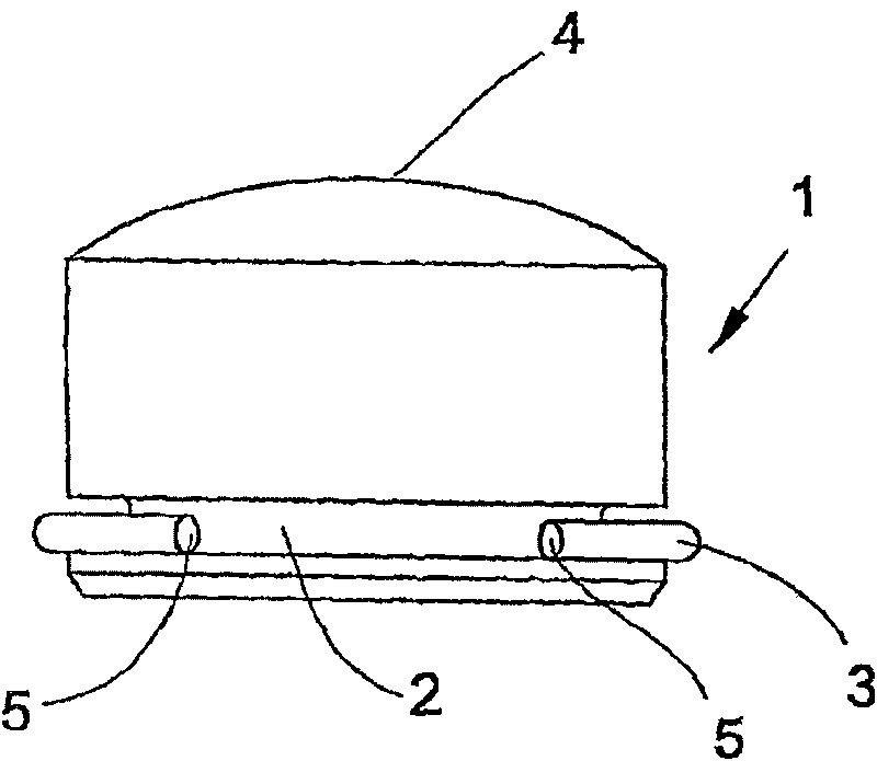
[0025] figure 1 The shown pre-assembled module comprises a coupling button 1 as well as a spring element 3. The coupling button 1 has a groove 2 in which the spring element 3 formed as a split ring is placed. The coupling button 1 is located opposite the groove 2. Convex curved joint surface at the end 4.

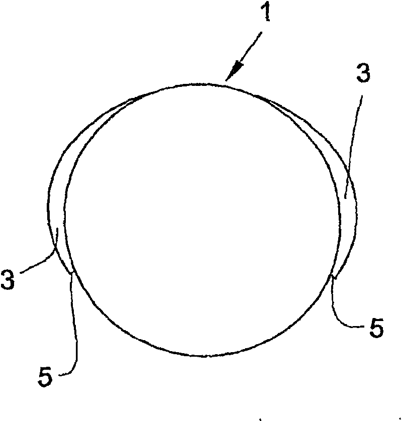
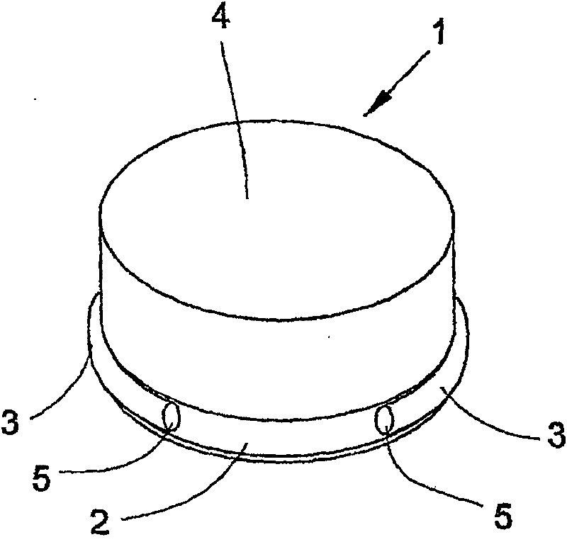
[0026] exist figure 2 The oval shape of the ring can be seen in the plan view of the coupling button 1 . The ring is open between free ends 5 which are completely separated from each other. Such as figure 2 view of and image 3 The free end 5 of the ring is located in the groove 2 as shown in the perspective view of . The part of the ring opposite the open part is completely in the groove 2 . The shape of the ring together with the groove 2 results in a firm hold on the coupling button 1 .

[0027] Figure 4 The coupling button 1 is shown during insertion into the hole 6 of the spindle 7 . To this end, the pre-assembled module comprising the coupling button 1 and...


PUM


Abstract

The invention relates to a bobbin coupling for spindles of a textile machine. Said bobbin coupling comprises coupling buttons (1), which are inserted into radially orientated, undercut bores (6) in the shaft of the spindle (7). The respective coupling button (1) can be displaced in the bore (6) and is pressed by its outwards facing end against the inner wall of a bobbin (11) that has been placed on the spindle (7) with the aid of centrifugal force, to create a frictional connection between the rotating spindle (7) and the bobbin (11). The coupling button (1) comprises a groove (2), which runsaround the periphery and into which a separate spring element is inserted. The spring element can be lowered into the groove (2) to mount the coupling button (1) and engages behind the undercut (10) once mounted. The bobbin coupling is used in spindles for spinning and winding machines.

Description

technical field [0001] The invention relates to a bobbin coupling, wherein the bobbin coupling comprises coupling buttons inserted into radially directed holes with undercuts in Move in the holes of these coupling buttons, and press the outwardly directed ends of these coupling buttons against the inner wall of the bobbin placed on the spindle under the action of centrifugal force, thereby forming a gap between the rotating spindle and the bobbin. Friction connection. Background technique [0002] A bobbin coupling is known from CH 464751, in which a plurality of button-like entraining bodies are arranged in blind bores evenly distributed around the spindle periphery. The entraining body, called the coupling button, is hollow and cap-shaped. The coupling buttons consist of elastic material so that they can be introduced into blind holes. In the installed state, they engage with their edges in undercuts introduced into the blind holes. A helical compression spring is resp...

Claims


Application Information

Patent Timeline
Patent Type & Authority Patents(China)
IPC IPC(8): D01H7/16
CPCD01H7/16
Inventor 赫尔穆特·施派泽克劳斯·塞费尔特克劳斯·梅特
Owner TEXPARTS GMBH
Why Eureka
Try Eureka