Opposed piston opposed cylinder free piston engine

An engine and engine cylinder technology, applied in the field of free-piston engines, can solve the problem that the power generated by the linear generator is not significantly effective.

Inactive Publication Date: 2007-05-02
FORD GLOBAL TECH LLC
View PDF0 Cites 23 Cited by
  • Summary
  • Abstract
  • Description
  • Claims
  • Application Information

AI Technical Summary

Problems solved by technology

However, linear generators are not significantly efficient at generating power - especially compared to traditional rotary generators

Method used


Image

  • Opposed piston opposed cylinder free piston engine
  • Opposed piston opposed cylinder free piston engine
  • Opposed piston opposed cylinder free piston engine

Examples


Embodiment Construction

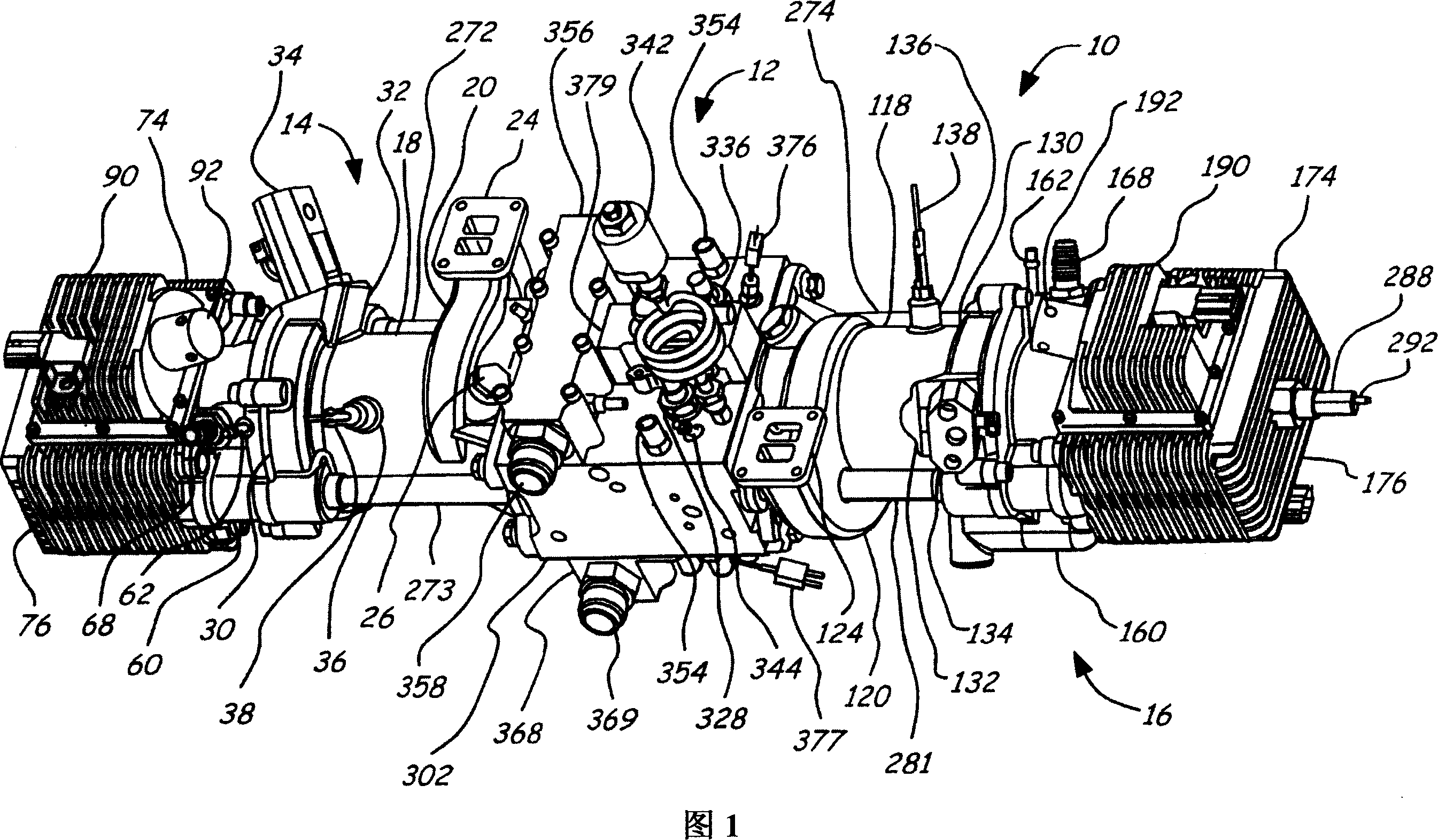
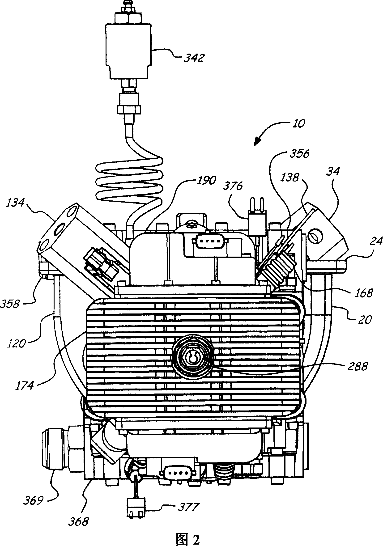
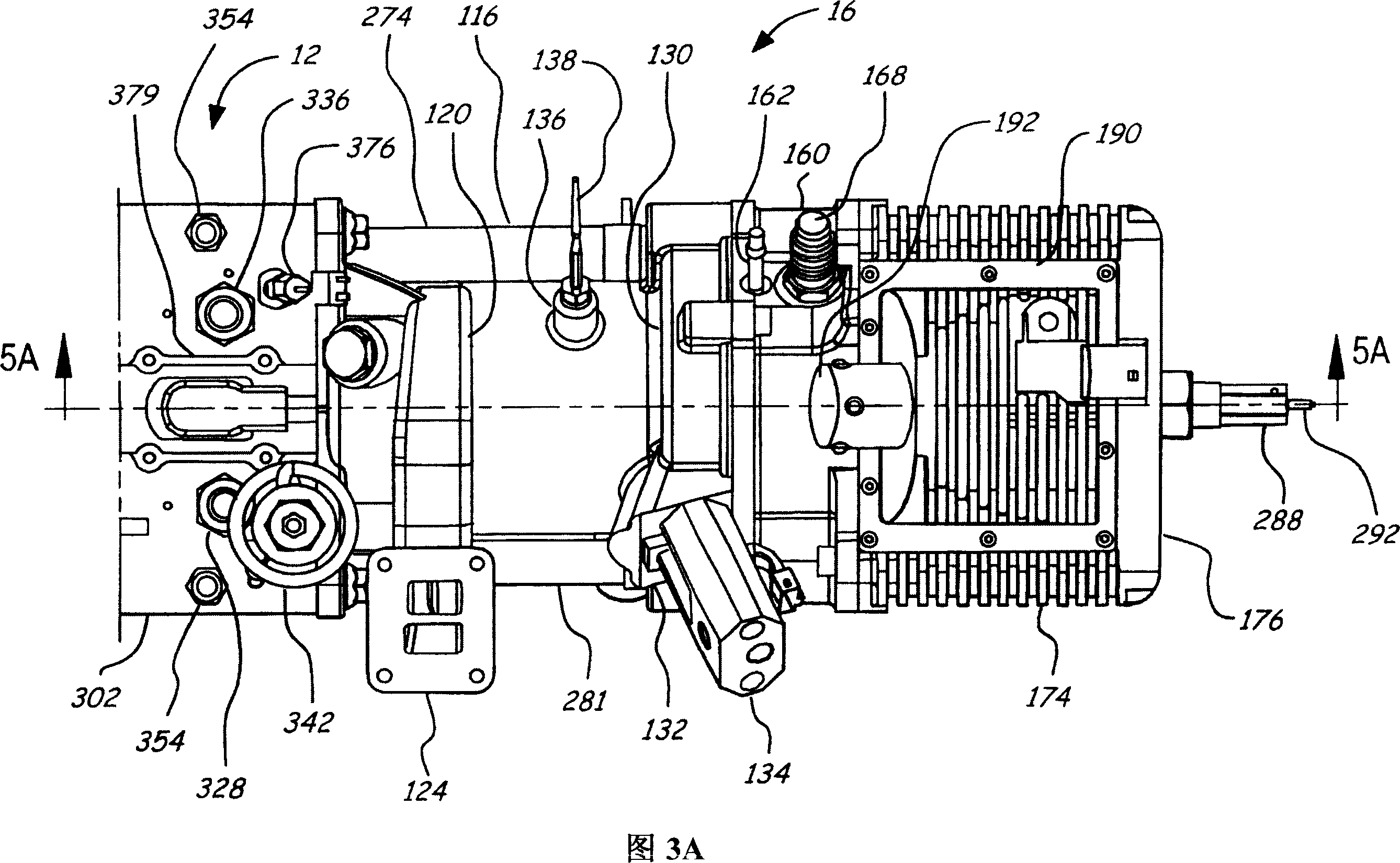
[0030] 1-11 show an opposed piston, opposed cylinder, hydraulic free piston engine 10 . The engine 10 includes a hydraulic pump block assembly 12, and a first piston / cylinder assembly 14 extending therefrom and a second piston / cylinder assembly 16 extending inversely from the hydraulic pump block assembly 12 such that they are in a row in a row. The timing of the first piston / cylinder assembly 14 is reversed from that of the second piston / cylinder assembly 16 . So when one is at top dead center, the other is at bottom dead center. Furthermore, the motion is along or parallel to a single axis of motion. The above-mentioned structure of the free piston engine can make the inherent balance of the engine better.

[0031] Additionally, the following description discloses an engine that not only stores energy produced by the engine in the form of pressurized fluid, but uses some of that pressurized fluid to start and sometimes to help control engine operation and maintain engine ...


PUM


Abstract

A free piston engine is configured with a pair of opposed engine cylinders located on opposite sides of a fluid pumping assembly. An inner piston assembly includes a pair of inner pistons, one each operatively located in a respective one of the engine cylinders, with a push rod connected between the inner pistons. The push rod extends through an inner pumping chamber in the fluid pumping assembly and forms a fluid plunger within this chamber. An outer piston assembly includes a pair of pistons, one each operatively located in a respective one of the engine cylinders, with at least one pull rod connected between the outer pistons. The pull rod extends through an outer pumping chamber in the fluid pumping assembly and forms a fluid plunger within this chamber.

Description

technical field [0001] The invention relates to a free-piston engine, in particular to a free-piston engine with a structure of opposed pistons and opposed cylinders. Background technique [0002] Conventionally, internal combustion engines operate with the movement of mechanically fixed pistons. For example, a conventional automotive internal combustion engine includes a crankshaft and connecting rod assembly that mechanically determines the movement of each piston within its respective cylinder. This type of engine is ideal because for any given point in the engine cycle, the position of each piston is known, which simplifies the timing and operation of the engine. While engines of the conventional type described above have seen significant improvements in efficiency in recent years, due to the nature of the engines, their efficiency remains limited. Especially since the mechanically fixed movement of the piston fixes the compression ratio, the power density is limited. ...

Claims


Application Information

Patent Timeline
Patent Type & Authority Applications(China)
IPC IPC(8): F04B17/00F04B35/00B60K1/00B60K16/00F02B71/00F02B71/04F02B75/28F04B19/00
CPCY02T10/90F02B75/28F02B71/04F04B19/003F01B11/006
Inventor 彼得·霍夫鲍尔
Owner FORD GLOBAL TECH LLC
Why Eureka
Try Eureka