Air charging system for an opposed piston opposed cylinder free piston engine

a charging system and piston technology, applied in the direction of combustion engines, machines/engines, electric control, etc., can solve the problems of large friction, limited efficiency, and limited power density, and achieve the effect of less overall friction to overcome, less friction in the overall, and a more effective homogeneous charg

Inactive Publication Date: 2005-10-25
FORD GLOBAL TECH LLC
View PDF11 Cites 55 Cited by
  • Summary
  • Abstract
  • Description
  • Claims
  • Application Information

AI Technical Summary

Benefits of technology

[0009]An advantage of an embodiment of the present invention is that an opposed piston, opposed cylinder (OPOC) configuration of a free piston engine allows for a more inherently balanced engine than other possible configurations of free piston engines. Moreover, the OPOC configured free piston engine, with relatively few major moving parts, will generally have less overall friction to overcome during engine operation than a crank engine.
[0010]An additional advantage of an embodiment of the present invention is that a variable compression ratio is not only more conducive for effective homogeneous charge, combustion ignition (HCCI) engine operation, but also allows the engine control strategy to be adaptable for a wide range of different fuels used for combustion. The OPOC free piston engine can achieve the compression energy needed for HCCI combustion, while more easily avoiding the generation of negative cycle work from early ignition than with a crankshaft engine. The air charging system significantly increases the air intake to the cylinders for each engine stroke, thus making HCCI operation more feasible.
[0011]A further advantage of an embodiment of the present invention is that the energy output from the engine can be stored as pressurized fluid or electrical power instead, if so desired.
[0012]Another advantage of an embodiment of the present invention is that efficient air charging is accomplished in order to create a desired high air intake pressure, even when employing an HCCI combustion process, which produces a lower exhaust temperature than conventional combustion process. Thus, the fresh air charge in the cylinder for each stroke is sufficiently increased, even when a high percentage exhaust gas recirculation (EGR) is employed to enhance the HCCI combustion process.
[0013]An additional advantage of an embodiment of the present invention is that it maintains a high trapping efficiency, with minimal loss of fresh air into the exhaust ports, as well as maintaining the desired amount of internal EGR.
[0014]Still another advantage of an embodiment of the present invention is that substantially symmetric intake exhaust ports may be used in order to achieve a high scavenge efficiency, without the need for asymmetrical port timing and the associated complicated mechanisms.

Problems solved by technology

While these conventional types of engines have seen great improvements in efficiency in recent years, due to the nature of the engines, that efficiency is still limited.
In particular, the power density is limited because the mechanically fixed motion of the pistons fixes the compression ratio.
Moreover, all of the moving parts that direct the movement of the pistons (and camshafts and engine valves as well) create a great deal of friction, which takes energy from the engine itself to overcome.
The resulting lower power density means that the engine will be larger and heavier than is desired.
Also, the flexibility in the engine design and packaging is limited because of all of the mechanical connections that must be made.
However, while this provides a significant increase in intake air pressure, it requires asymmetrical port timing, with complicated mechanisms and / or a loss of scavenge efficiency and trapping efficiency (i.e., loss of fresh air out of the exhaust ports).

Method used


Image

  • Air charging system for an opposed piston opposed cylinder free piston engine
  • Air charging system for an opposed piston opposed cylinder free piston engine
  • Air charging system for an opposed piston opposed cylinder free piston engine

Examples


Embodiment Construction

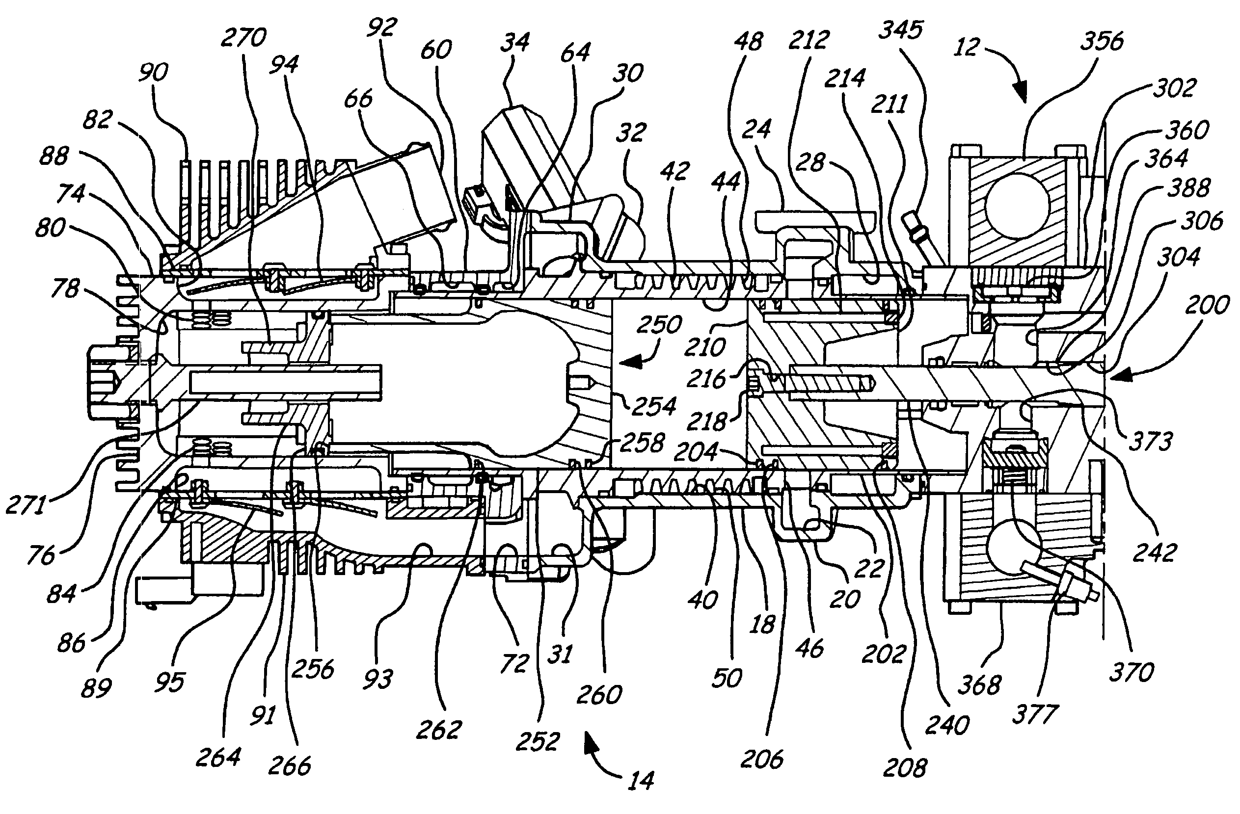
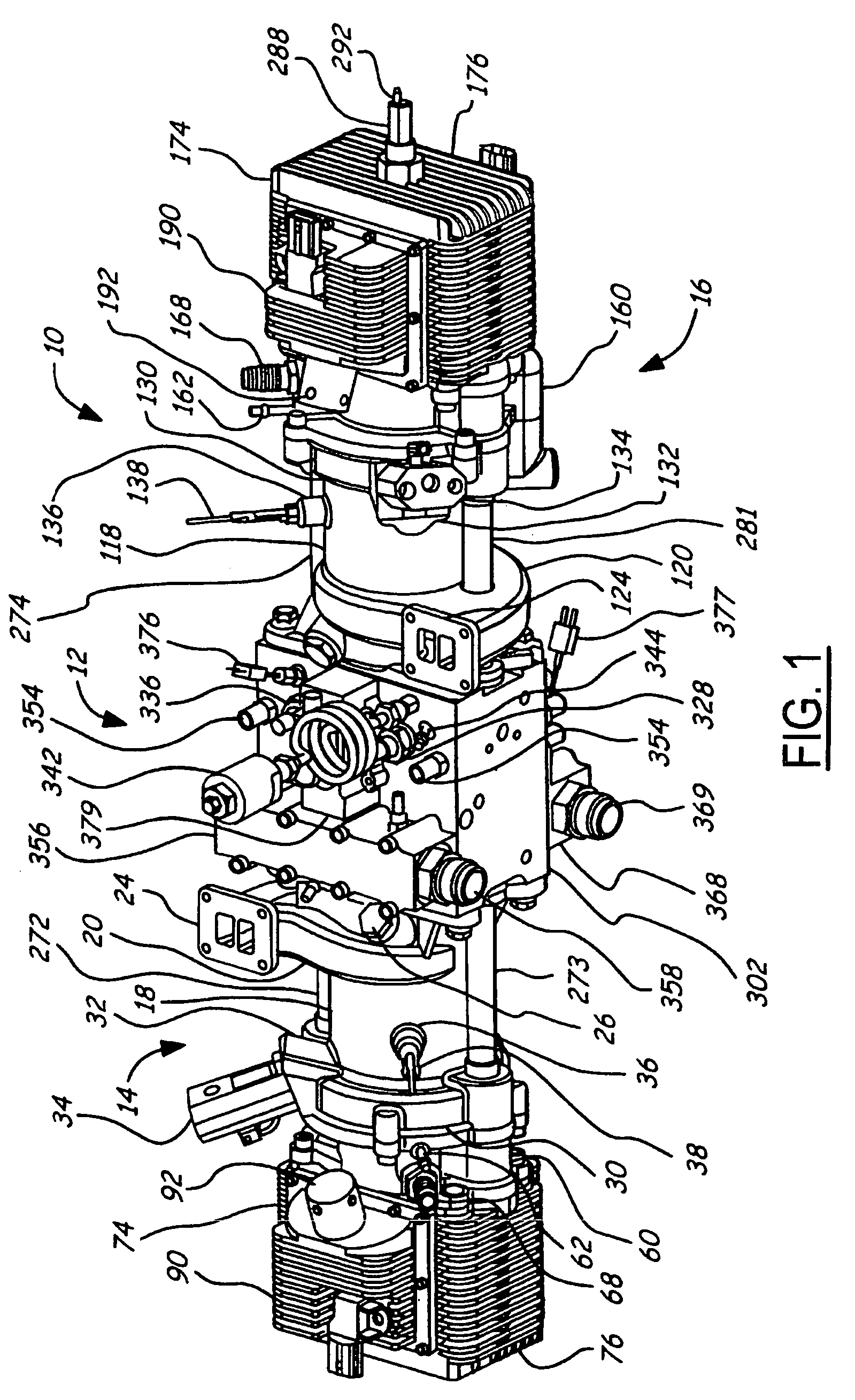
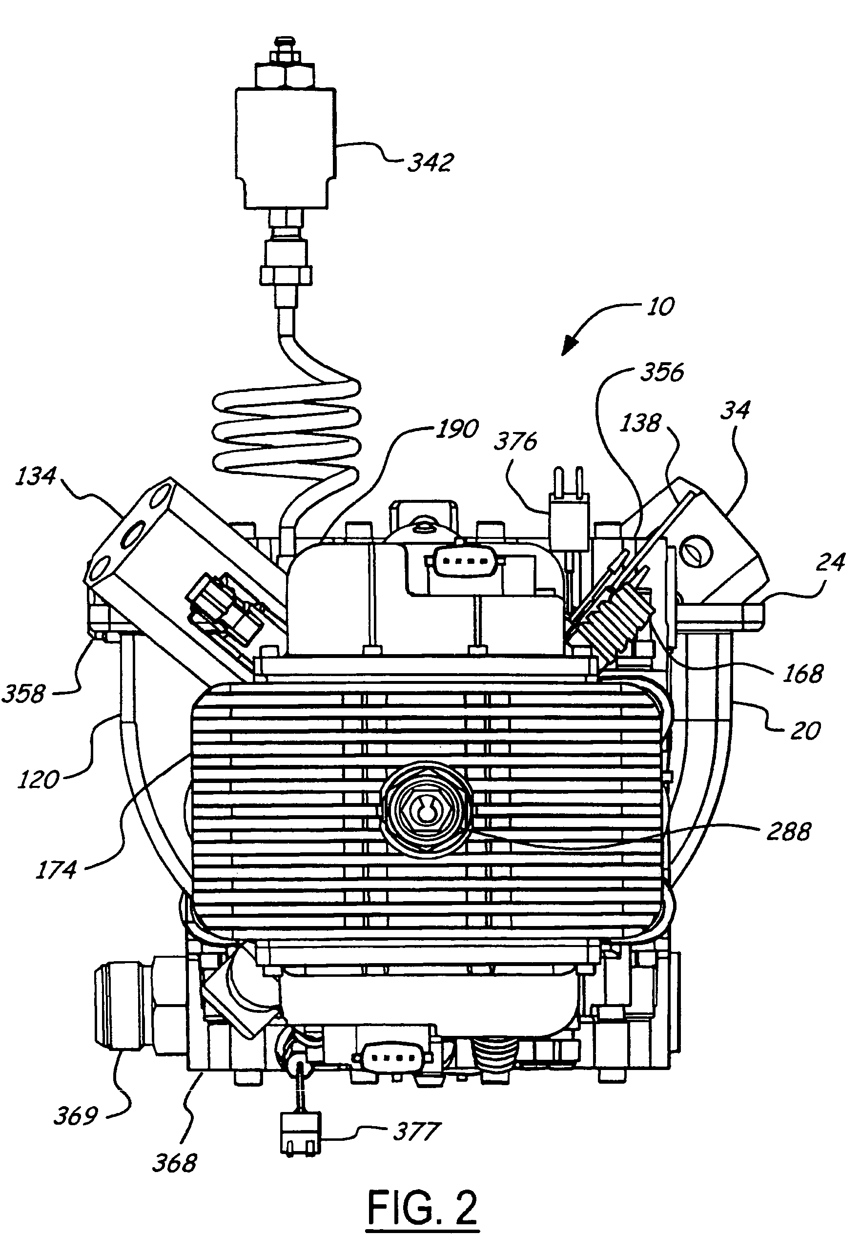
[0033]FIGS. 1–11 and 14 illustrate an opposed piston, opposed cylinder, hydraulic, free piston engine 10. The engine 10 includes a hydraulic pump block assembly 12, with a first piston / cylinder assembly 14 extending therefrom, and a second piston / cylinder assembly 16 extending from the hydraulic pump block assembly 12 in the opposite direction so they are in line. The timing of the first piston / cylinder assembly 14 is opposite to the timing of the second piston / cylinder assembly 16. Thus, when one is at top dead center, the other is at bottom dead center. Moreover, the motion is along or parallel to a single axis of motion. This configuration of free piston engine allows for a more inherently balanced engine.

[0034]The first piston / cylinder assembly 14 includes a first cylinder jacket 18, which mounts to the hydraulic pump block assembly 12. The first cylinder jacket 18 includes a first exhaust gas scroll 20, which is located adjacent to the hydraulic pump block assembly 12. The inte...


PUM


Abstract

A free piston engine is configured with a pair of opposed engine cylinders located on opposite sides of a fluid pumping assembly. An inner piston assembly includes a pair of inner pistons, one each operatively located in a respective one of the engine cylinders, with a push rod connected between the inner pistons. The push rod extends through an inner pumping chamber in the fluid pumping assembly and forms a fluid plunger within this chamber. An outer piston assembly includes a pair of pistons, one each operatively located in a respective one of the engine cylinders, with at least one pull rod connected between the outer pistons. The pull rod extends through an outer pumping chamber in the fluid pumping assembly and forms a fluid plunger within this chamber. Each outer piston cooperates with an integrated scavenge pump in order to compress the charge air, thus significantly increasing the air charge density into the engine cylinders for each stroke of the engine.

Description

BACKGROUND OF INVENTION[0001]The present invention relates to free piston engines, and more particularly to free piston engines having an opposed piston opposed cylinder configuration.[0002]Conventionally, internal combustion engines have operated with the motion of the pistons mechanically fixed. For example, a conventional internal combustion engine for a motor vehicle includes crankshaft and connecting rod assemblies that mechanically determine the motion of each piston within its respective cylinder. This type of engine is desirable because the position of each piston is know for any given point in the engine cycle, which simplifies timing and operation of the engine. While these conventional types of engines have seen great improvements in efficiency in recent years, due to the nature of the engines, that efficiency is still limited. In particular, the power density is limited because the mechanically fixed motion of the pistons fixes the compression ratio. Moreover, all of the...

Claims


Application Information

Patent Timeline
Patent Type & Authority Patents(United States)
IPC IPC(8): F02B71/00F02B25/26F02B29/04F02B33/04F02B37/00F02B71/06F02D41/30
CPCF02B25/26F02B29/0412F02B33/04F02B37/00F02B71/00F02B71/06F02D41/3035Y02T10/146Y02T10/144Y02T10/12
Inventor CARLSON, CLIFFPENG, LIXIN
Owner FORD GLOBAL TECH LLC
Why Eureka
Try Eureka