Composite pipe lining, method and apparatus for installing composite lining

A technology of composite lining and pipeline, applied in the direction of mechanical equipment, hoses, pipes, etc., can solve the problems of difficult and expensive lining of large-diameter pipelines

Inactive Publication Date: 2007-05-02
诺曼·怀斯特·贝拉米 +1
View PDF6 Cites 13 Cited by
  • Summary
  • Abstract
  • Description
  • Claims
  • Application Information

AI Technical Summary

Problems solved by technology

However, in the water and sewer pipe industry, lining large diameter pipes i

Method used


Image

  • Composite pipe lining, method and apparatus for installing composite lining
  • Composite pipe lining, method and apparatus for installing composite lining
  • Composite pipe lining, method and apparatus for installing composite lining

Examples


Example Embodiment

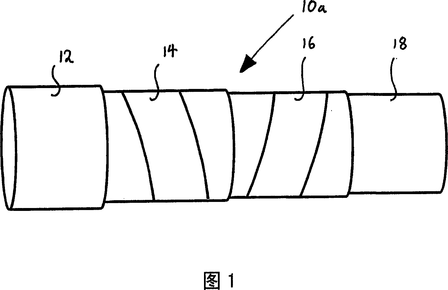
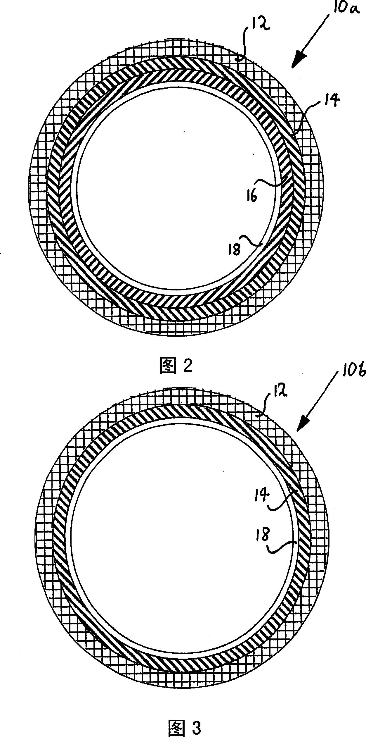
[0072] In Figures 1 and 2, the first embodiment of the composite liner is generally shown at 10a. In operation, the composite liner 10a is arranged in the main pipe 12. The liner 10a includes outer and inner structural layers 14, 16 for providing structural integrity, and a sealing layer 18 for providing fluid impermeability.

[0073] Each structural layer 14, 16 includes a lining strip tightly wound in a spiral shape, and each turn is substantially in contact with each adjacent turn. Thus, each strip forms a substantially continuous, cylindrical and tubular structure. The lining strip of the outer structural layer 14 is wound onto the inner surface of the main pipe 12 in the first spiral direction. Similarly, the lining strips of the inner structural layer 16 are wound onto the inner surface of the outer structural layer 14 in the opposite spiral direction.

[0074] Each liner strip 14, 16 has an appropriate thickness so that when wound, each liner strip 14, 16 forms a substantia...


PUM


Abstract

A composite lining for a pipe comprising a structural layer for providing structural integrity and a containment layer for providing fluid impermeability. The structural layer comprising at least one strip of lining material arranged to form a substantially continuous lining within said pipe. A method for lining a pipe with said composite lining. A structure and method for testing the fluid integrity of said containment layer. Apparatus for installing said structural and containment layers in said pipe.

Description

Technical field [0001] The invention relates to a composite lining for pipelines, a method for installing the composite lining and a device for installing the composite lining. Background technique [0002] As the gas and water management department is well-known, pipeline leakage is a major problem. This problem is caused by the cost of interruptions and the mixing of interruptions caused by correcting the leak by repairing or replacing faulty gas, water, and sewer pipes when the leak occurs. For gas pipelines, where any leakage is dangerous, leakage is a particular problem, and for water pipelines, where leakage is typically the cause of more than 30% of the average loss between the reservoir and the tap , Leakage is also a special problem. Many pipelines need to be refurbished, and management usually seeks long-term solutions rather than piecemeal repairs. [0003] One solution to extend the life of existing pipes is to reline them with appropriate materials. For example, ther...

Claims


Application Information

Patent Timeline
IPC IPC(8): F16L11/08F16L11/24F16L55/1645
Inventor 诺曼·怀斯特·贝拉米尼尔·迈克尔·贝拉米
Owner 诺曼·怀斯特·贝拉米
Why Eureka
Try Eureka