
Spot soldering fixture and spot soldering process

A fixture and spot welding technology, which is applied in welding equipment, manufacturing tools, resistance welding equipment, etc., can solve the problems of difficult spot welding, low material utilization rate, and easy occurrence of defective products, so as to reduce the welding defect rate and improve Spot welding quality, the effect of improving the quality of solder joints

Inactive Publication Date: 2012-07-18
DONGGUAN NVT TECH
View PDF6 Cites 13 Cited by
  • Summary
  • Abstract
  • Description
  • Claims
  • Application Information

AI Technical Summary

Problems solved by technology

However, since the bumps of the copper feet of the fuse are set upwards, and the aluminum-nickel composite strip has a double-layer structure, it is difficult to spot weld, which may easily lead to false welding or false welding, and the pulling force cannot meet the requirements, so Prone to a large number of defective products, affecting product quality
In addition, false welding and false welding need special personnel to select them before repairing welding, which is time-consuming and labor-intensive, and affects production capacity.
[0005] In addition, increasing the energy output and other related parameters of the spot welding equipment can avoid false welding and virtual welding, but it will also cause undesirable phenomena such as over-welding, explosion and welding penetration.
Among them, the fire explosion is particularly serious, resulting in the scrapping of the fuse, low material utilization rate, and low efficiency. The fire explosion phenomenon causes sparks to splash, which may damage adjacent devices and even injure the operator.

Method used


Image

  • Spot soldering fixture and spot soldering process
  • Spot soldering fixture and spot soldering process
  • Spot soldering fixture and spot soldering process

Examples


Embodiment Construction

[0024] The present invention will be described in further detail below in conjunction with the examples and the accompanying drawings, but the implementation of the present invention is not limited thereto.

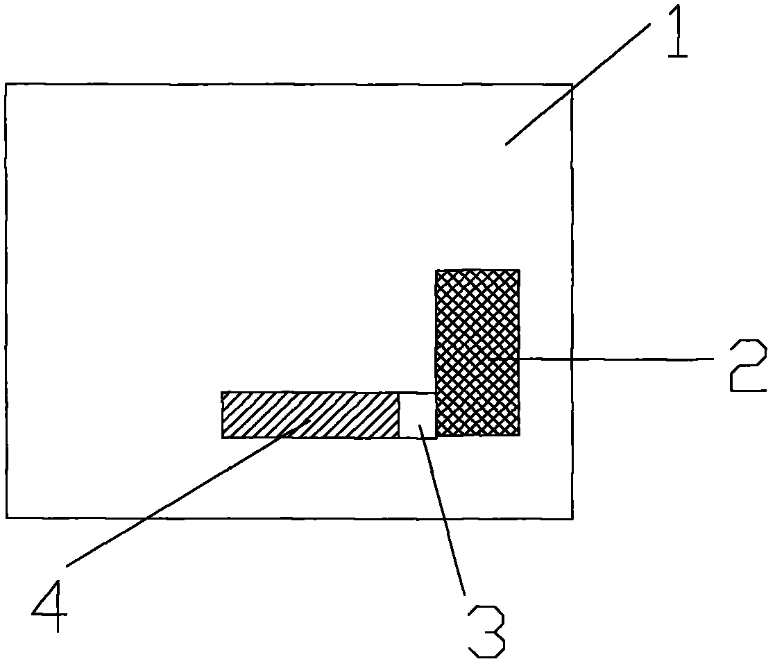
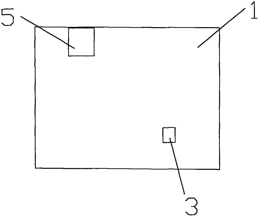
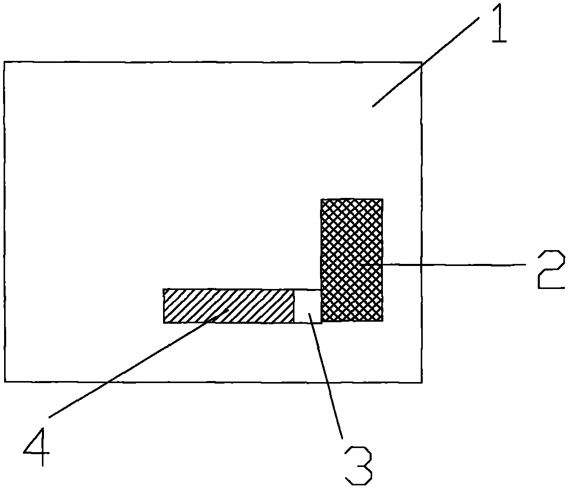
[0025] Such as figure 1 and 2 As shown, the spot welding jig of the present invention includes a jig body 1 and a cell placement area 2 and a fuse placement area 3 arranged on the jig body, and an arrangement between the cell placement area 2 and the fuse placement area 3 Have escape hole 4. The cell placement area 2 and the fuse placement area 3 are arranged vertically. The cell placement area 2 is a groove structure. The fuse placement area 3 is a groove structure. The electric core is provided with tabs made of aluminum-nickel composite tape.

[0026] Depend on figure 2 It can be seen that the fixture main body 1 is also provided with an adjuster 5 for adjusting the height of the welding bottom needle.

[0027] When using this fixture for spot welding operation...


PUM


Abstract

The invention belongs to the technical field of soldering, and particularly relates to a spot soldering fixture, which is used in a spot soldering process capable of avoiding pseudo soldering, false soldering and bursting, and is high in soldering efficiency. The spot soldering fixture comprises a fixture body, a cell storage area and a fuse storage area, and an avoidance hole is reserved between the cell storage area and the fuse storage area. Compared with the prior art, the spot soldering fixture has the advantages that a fuse and a metal strap can be effectively positioned, the height of a soldering pin can be adjusted, spot soldering quality can be improved, soldering reject ratio can be decreased, production efficiency can be improved, and cost can be saved. Besides, the invention further discloses the spot soldering process using the spot soldering fixture.

Description

technical field [0001] The invention belongs to the field of welding technology, and in particular relates to a spot welding process and a spot welding fixture used therein which can avoid virtual welding, false welding and explosion and have high welding efficiency. Background technique [0002] With the continuous development of electronic equipment, the battery as the power supply of the electronic equipment has also been greatly developed; and with the miniaturization of the electronic equipment, the battery is also correspondingly developing towards thinner and lighter weight. [0003] A battery generally includes a cell, a protective plate located at the front of the cell, and other related structural components, such as a front cover, a rear cover, and a casing. A fuse is generally installed on the protection board. When the temperature of the battery rises to a certain temperature, the fuse is disconnected to prevent the battery from exploding. The connection betwee...

Claims


Application Information

Patent Timeline
Patent Type & Authority Applications(China)
IPC IPC(8): B23K11/11B23K11/36
Inventor 卫建军周和玲
Owner DONGGUAN NVT TECH
Learn More