Tensile test device

A technique for tensile testing and installation, applied to measuring devices, applying stable tension/pressure to test material strength, instruments, etc., can solve the problem of inability to parallel the vertical direction of the pin 104, deformation or crooked of the pin 104, and damage to the electronics Problems such as component appearance, to avoid damage to electronic components, to achieve reliable results, to improve the efficiency of the production process and product quality

Inactive Publication Date: 2012-10-17
ASKEY TECH JIANGSU +1
View PDF6 Cites 13 Cited by
  • Summary
  • Abstract
  • Description
  • Claims
  • Application Information

AI Technical Summary

Problems solved by technology

[0005] However, the known tensile test device 1 must weld the pin 104 and the test lead 110 before performing the tensile test, which will cause thermal stress inside the pin 104 and have a negative impact on the material strength of the pin 104 itself; and When performing a tensile test, the clamping action of the fixture 15 to fix the body 102 will also cause external stress, causing the body 102 to be deformed under pressure, resulting in damage to the appearance, and more likely to damage the internal structure; , locking degree and position are not quantified, so that the parameters of each test are inconsistent, thereby affecting the test results; It cannot be parallel to the initial upright direction of the pin 104, so the pulling force is not completely applied to the electronic component 100, and it is hung on the push-pull gauge 20 by the hook portion 112 at one end of the test lead 110, when the main body 102, When the position of the pin 104, the test lead 110 and the hook 112 are not in a straight line, it will affect the direction of the applied pulling force and lead to the generation of non-vertical component force
[0006] Therefore, the above-mentioned known tensile test device will damage the appearance of the electronic component to be tested, and the result will be affected due to the generation of the component force of the tensile force, and the process will be cumbersome and inconvenient, resulting in poor efficiency; therefore, a convenient operation, testing process A stable and reliable pin pull test device is necessary to improve the efficiency of the production process and product quality

Method used


Image

  • Tensile test device
  • Tensile test device
  • Tensile test device

Examples


Embodiment Construction

[0057] In order to fully understand the purpose, features and effects of the present invention, the present invention will be described in detail with the help of the following specific examples and accompanying drawings.

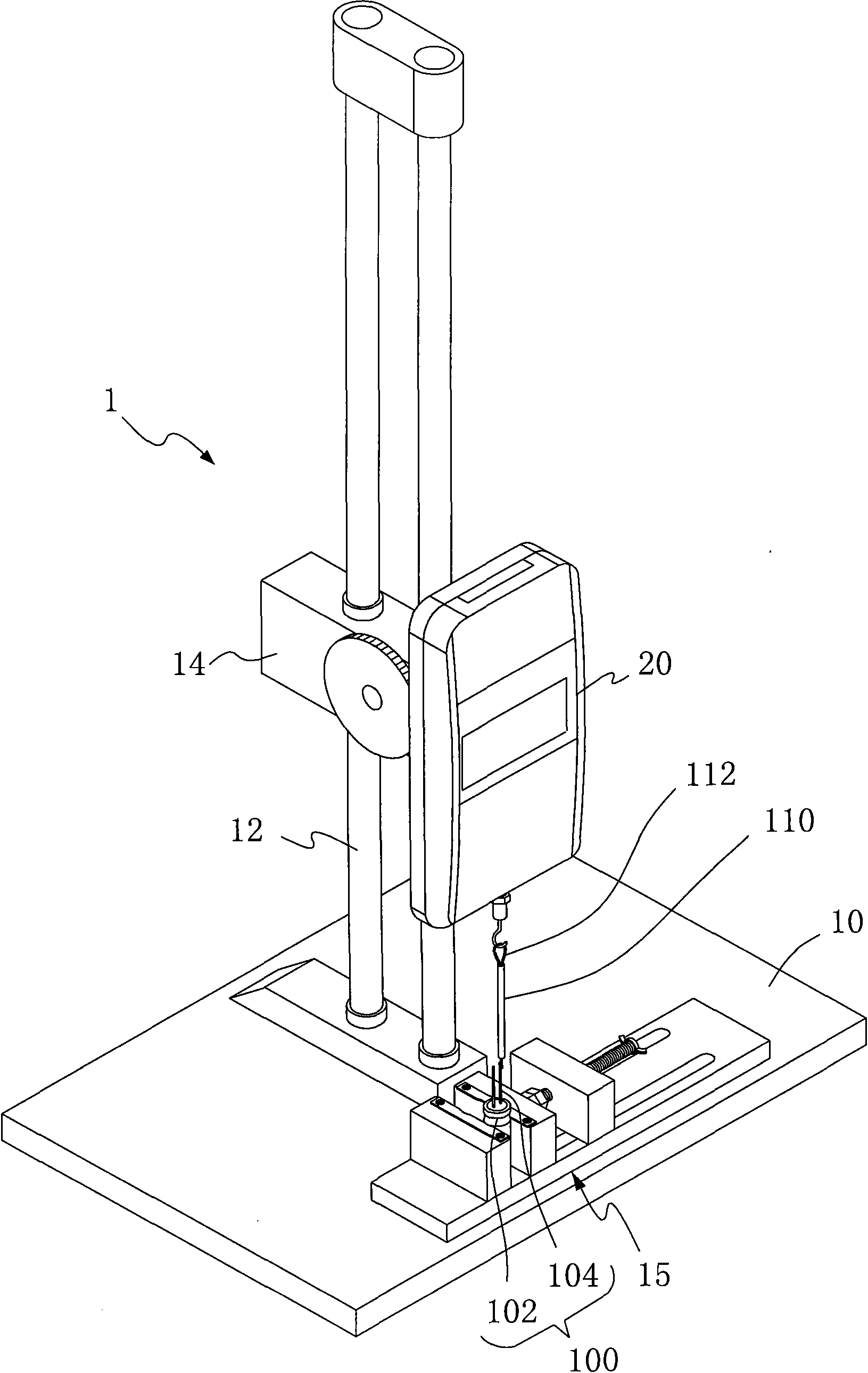
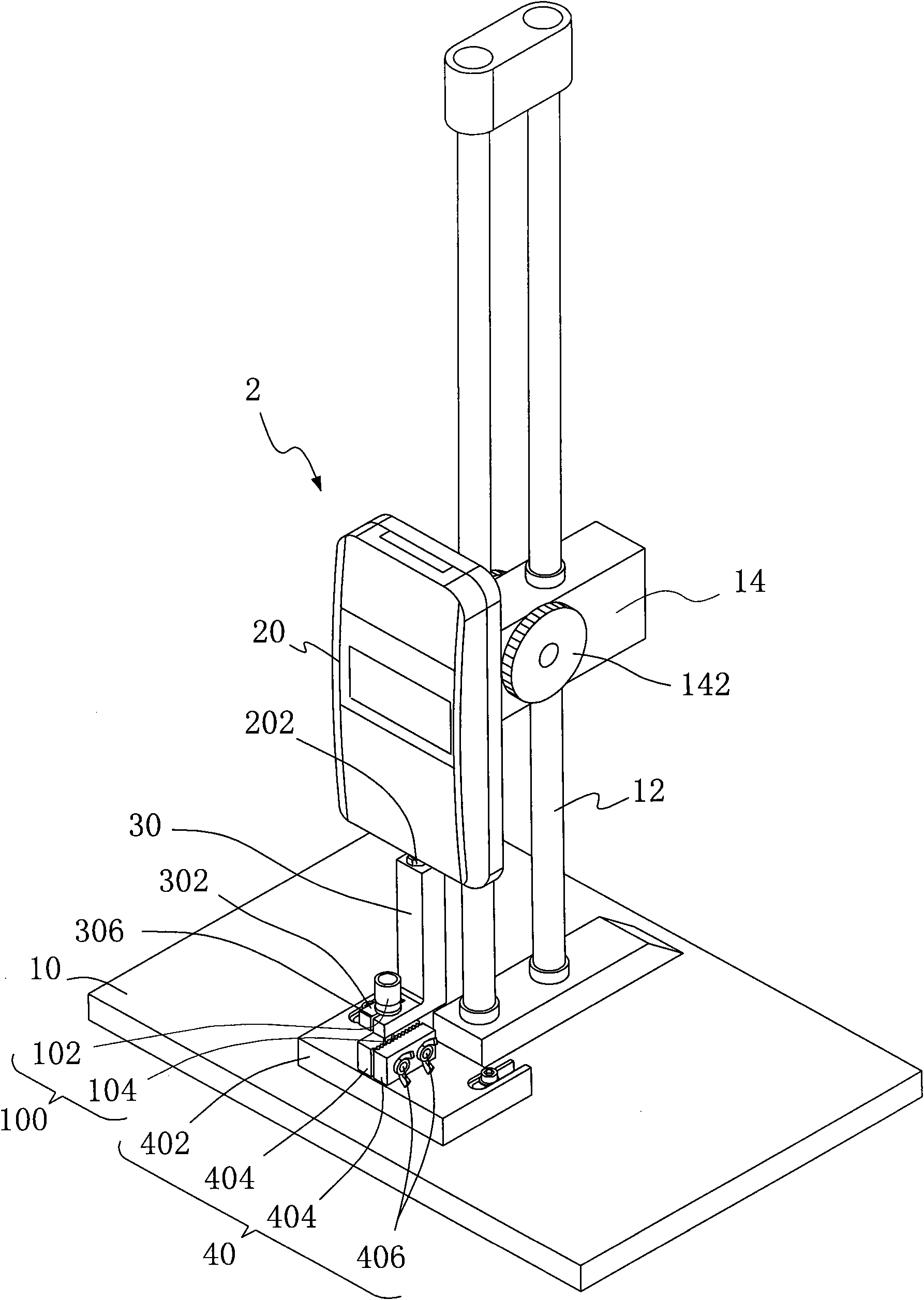
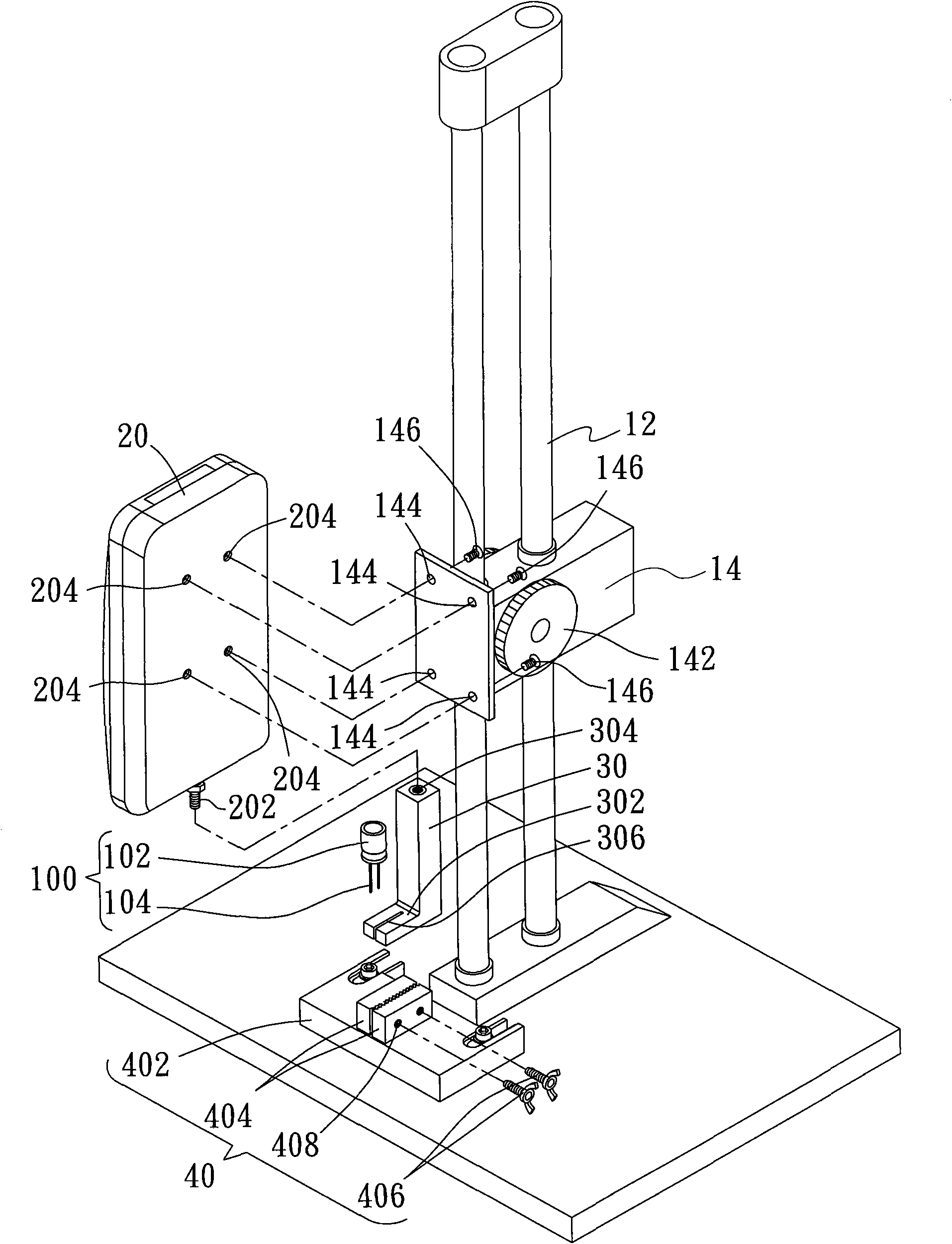
[0058] refer to figure 2 , is a three-dimensional schematic diagram of a tensile test device according to an embodiment of the present invention. The tensile test device 2 is used to conduct a tensile test of the electronic component 100 to test the bonding strength between the body 102 and the pin 104 . At figure 2 Among them, the tensile test device 2 includes a base 10, a push-pull force gauge 20, a hanger 30 and a clamp 40; wherein, the base 10 has a support frame 12 and a mounting portion 14 located on the support frame 12, and the push-pull force gauge 20 is installed on the installation part 14 and has a stretching part 202; the hanger 30 is connected to the stretching part 202 for hanging the body 102 and exposing the pins 104 towards the base 10...


PUM


Abstract

The invention provides a tensile test device for tensile test of binding strength between an electronic component body and a pin. The device comprises a base, a push and pull dynamometer, a rack and a fixture. The base comprises a support frame and an installation part; the push and pull dynamometer is mounted on a mounting portion and contains an extension part; the rack is connected to the extension part, and is used for hanging the body and towards the exposed pin on the base; and the fixture is arranged on the base, right opposite to the rack and for clamping the pin. The invention can avoid electronic component body deformation caused by a known tensile test device and eliminate complex steps of welding and welding removal of the pin and a test wire, and can solve problems caused by component force in the test, thereby having the advantages of convenient operation, stable test process, improvement on test efficiency and reliability.

Description

technical field [0001] The invention relates to a tensile test device, in particular to a tensile test device for combining strength of a body and pins of an electronic component. Background technique [0002] Currently commonly used electronic components usually have a body and pins connected to it (also known as pins, lead wires, guide pins, cathode / anode terminals or cathode / anode wires), such as resistors, capacitors, inductors, diodes, and transistors. The pins are used to electrically connect the body of the electronic component and the circuit board; wherein, the bonding strength between the body of the electronic component and the pins affects the stability of the electrical connection of the circuit board, thereby affecting the overall use and quality of the electronic product. Therefore, in the manufacturing process of various electronic components, pin strength tensile tests must be carried out to achieve product requirements or verification standards that the bod...

Claims


Application Information

Patent Timeline
Patent Type & Authority Applications(China)
IPC IPC(8): G01N3/08G01N3/02G01N3/04
Inventor 沈鑫欧文祥谢青峰
Owner ASKEY TECH JIANGSU
Why Eureka
Try Eureka