
Variable focus lens

A focus lens and lens technology, applied in the direction of lenses, optics, instruments, etc., can solve the problems of high voltage and impracticality, and achieve the effect of large zoom factor

Inactive Publication Date: 2007-05-02
KONINKLIJKE PHILIPS ELECTRONICS NV
View PDF1 Cites 0 Cited by
  • Summary
  • Abstract
  • Description
  • Claims
  • Application Information

AI Technical Summary

Problems solved by technology

For portable applications, such as camcorders or similar, this voltage is too high to be practical, and a lower voltage is desired if possible

Method used


Image

  • Variable focus lens
  • Variable focus lens
  • Variable focus lens

Examples


Embodiment Construction

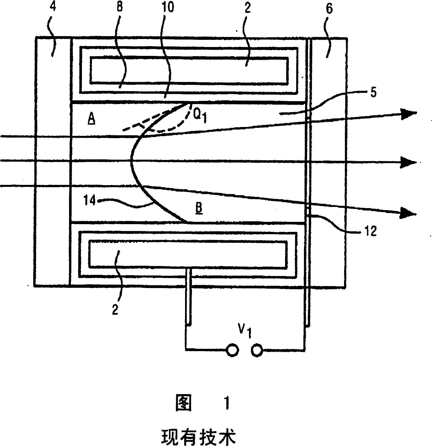
[0022] In order to understand the operation of embodiments of the present invention, it is instructive to review the operation of the prior art electrowetting lens shown in FIG. 1 . Such lenses are described in detail in WO 03 / 069380, and reference is made to this publication for a general understanding of the operation and construction of such lenses.

[0023] For the purposes of the present invention, the following brief description will suffice.

[0024] The lens shown in Figure 1 comprises a cylindrical first electrode 2 forming a capillary, which is sealed by means of a transparent front group 4 and a transparent rear group 6, forming a fluid chamber 5 containing two fluids. Electrode 2 may be a conductive coating applied to the inner wall of the tube.

[0025] Two fluids are composed of two immiscible liquids, namely an electrically insulating first liquid A (such as silicone oil or alkane, referred to herein as "oil") and a conductive second liquid B (such as containin...


PUM


Abstract

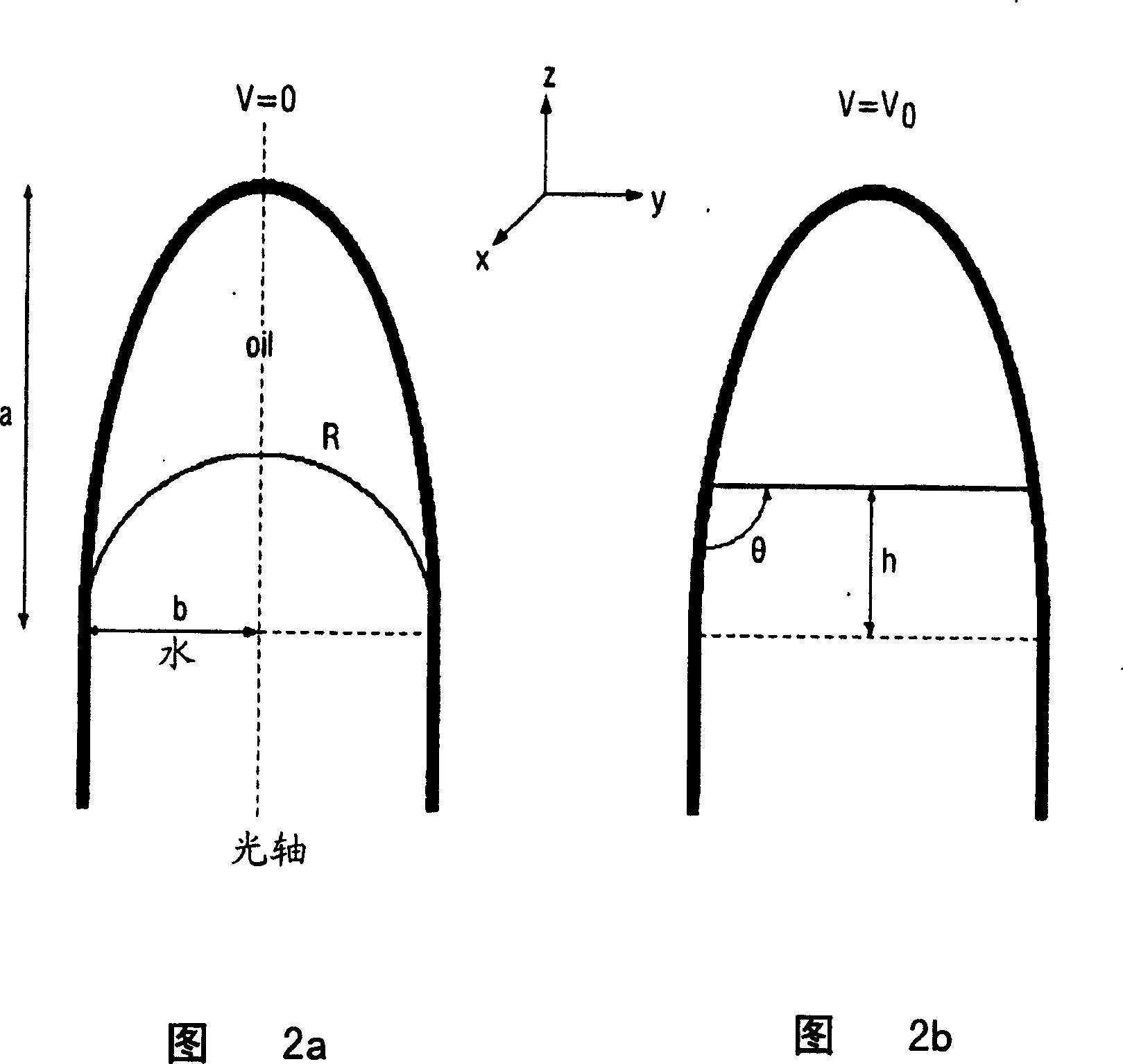
Disclosed is a variable focus lens, having an optical axis, comprising: a fluid chamber, the fluid chamber comprising a first fluid and an axially displaced second fluid, the fluids being non-miscible, in contact over a meniscus and having different indices of refraction; a fluid contact layer arranged on the inside of the chamber wall; a first electrode separated from the first fluid and second electrode by the fluid contact layer; a second electrode acting on the second fluid; the fluid contact layer having a wettability by the second fluid which varies under the application of a voltage between the first electrode and the second electrode, such that the shape of the meniscus varies in dependence on said voltage; wherein the fluid chamber is shaped such that an angle formed between the wall of the chamber and the optical axis decreases along the length of the optical axis.

Description

technical field [0001] The present invention relates to a variable focus lens comprising a unit having first and second fluids held in contact on a meniscus. The shape of the meniscus, and thus the focal point of the lens, can be controlled by applying a voltage to the cell. Such a lens is sometimes called an electrowetting lens. Background technique [0002] A fluid is a substance that can change its shape in response to any force, that has a tendency to flow or conform to the contours of the chamber containing it, including gases, vapors, liquids, and mixtures of solids and liquids that are capable of flow. [0003] In general, relatively high voltages, typically 100 volts, are required to control the meniscus in a typical electrowetting lens. For portable applications, such as camcorders or similar, this voltage is too high to be practical, and a lower voltage is desired if possible. Two known ways to reduce the required voltage are to reduce the thickness of the insul...

Claims


Application Information

Patent Timeline
IPC IPC(8): G02B3/14G02B26/02
CPCG02B26/005G02B3/14G02B26/004
Inventor B·H·W·亨德里克斯S·凯帕
Owner KONINKLIJKE PHILIPS ELECTRONICS NV
Learn More