Shell structure of water meter

A shell structure and shell technology, used in liquid/fluid solid measurement, measuring devices, instruments, etc., can solve the problems of short service life, complex structure, poor corrosion resistance, etc., and achieve long service life and good structural strength. Effect

Inactive Publication Date: 2007-05-16
TIANJIN JINNAN KAIDA ELECTRONIC CO LTD
View PDF0 Cites 5 Cited by
  • Summary
  • Abstract
  • Description
  • Claims
  • Application Information

AI Technical Summary

Problems solved by technology

[0002] The commonly used water meter housings are integral and inlaid. The integral type is metal casting, which has poor corrosion resistance, secondary pollution to the

Method used


Image

  • Shell structure of water meter

Examples


Example Embodiment

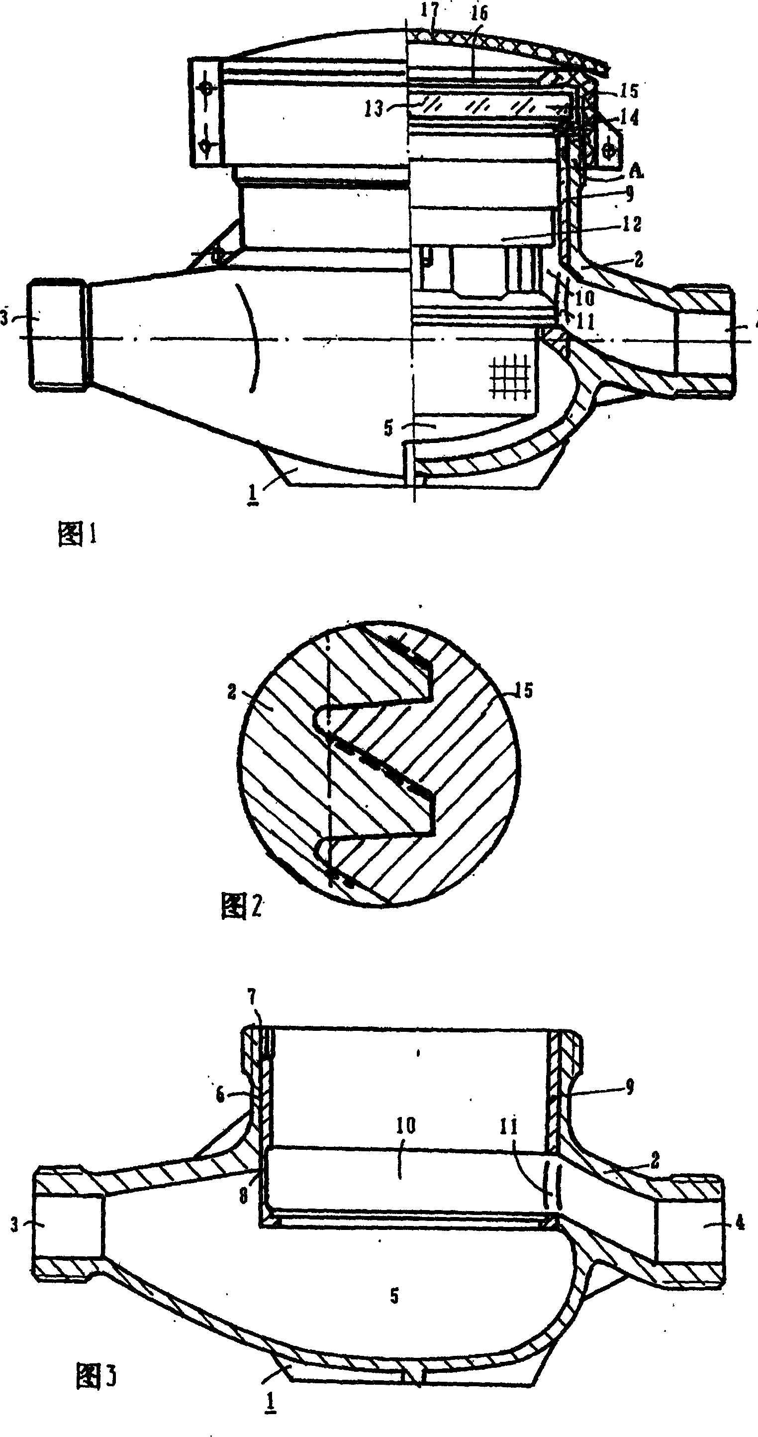
[0009] Please refer to the figure, a housing structure of a water meter. The housing 1 is composed of a housing and a water ring tank. The housing 2 has a fluid inlet 3 and an outlet 4, a movement cavity 5, and a cylindrical water that are separately placed at both ends of the housing. Ring groove cavity 6, the upper mouth of the water ring groove cavity is larger than the lower mouth, the water ring groove body 9 is cylindrical, and the inner circumference of the water ring groove 10 is an open ring. The outer circumference of the water ring groove body and the water ring The inner circumference of the groove cavity 6 is in a sealed fit, and the water ring groove body 9 is embedded in the water ring groove cavity 6 of the housing 2, so that the opening 11 of the water ring groove communicates with the outlet 4 of the housing to form the housing 1. The body is equipped with a water meter movement 12, the lower part of the movement is placed in the movement cavity 5, the upper part...


PUM


Abstract

This invention relates to water meter shell structure composed of shell and water ring tank, wherein, the shell core chamber and column water ring tank chamber with top mouth larger than down one; the water ring tank is of round cylinder with inside circle of round ring tank; the water ring tank outside and water tank inside are matched with water tank imbedded into water ring chamber to connect tank open to shell exit to form shell; the shell is fixed with water machine chip into machine chip matched with water ring tank.

Description

technical field [0001] The invention relates to a shell structure of a water meter. Background technique [0002] The commonly used water meter shells are integral and inlaid. The integral type is metal casting, which has poor corrosion resistance, secondary pollution to the water flowing through the water meter, and reduced measurement accuracy. The butt joint type has poor bonding firmness, short service life, and complex structure. Poor sealing. Contents of the invention [0003] The object of the present invention is to overcome the above defects and provide a shell structure of a water meter. [0004] The technical solution of the present invention is a housing structure of a water meter, which is characterized in that it includes an inlet and an outlet, a housing of a movement chamber and a water ring groove, the movement in the housing, and the window at the upper end of the housing are connected with In the middle cover, the housing has a shell with a cylindrical...

Claims


Application Information

Patent Timeline
IPC IPC(8): G01F15/14G01F15/00
Inventor 崔连凯
Owner TIANJIN JINNAN KAIDA ELECTRONIC CO LTD
Why Eureka
Try Eureka