
Method and system of video frequency velometer

A technology of field of view and speed, applied in parts of TV systems, traffic control systems, devices using optical methods, etc., can solve problems such as accuracy less than ±1km/h, influence, and difficulty in obtaining accurate data

Inactive Publication Date: 2007-05-16
王海燕
View PDF0 Cites 11 Cited by
  • Summary
  • Abstract
  • Description
  • Claims
  • Application Information

AI Technical Summary

Problems solved by technology

Close-range speed measurement is seriously affected by the vehicle model. If it is installed on a fixed gantry and looked down for measurement, it is difficult to obtain accurate data, and the accuracy cannot reach ±1km / h

Method used


Image

  • Method and system of video frequency velometer
  • Method and system of video frequency velometer
  • Method and system of video frequency velometer

Examples


Embodiment Construction

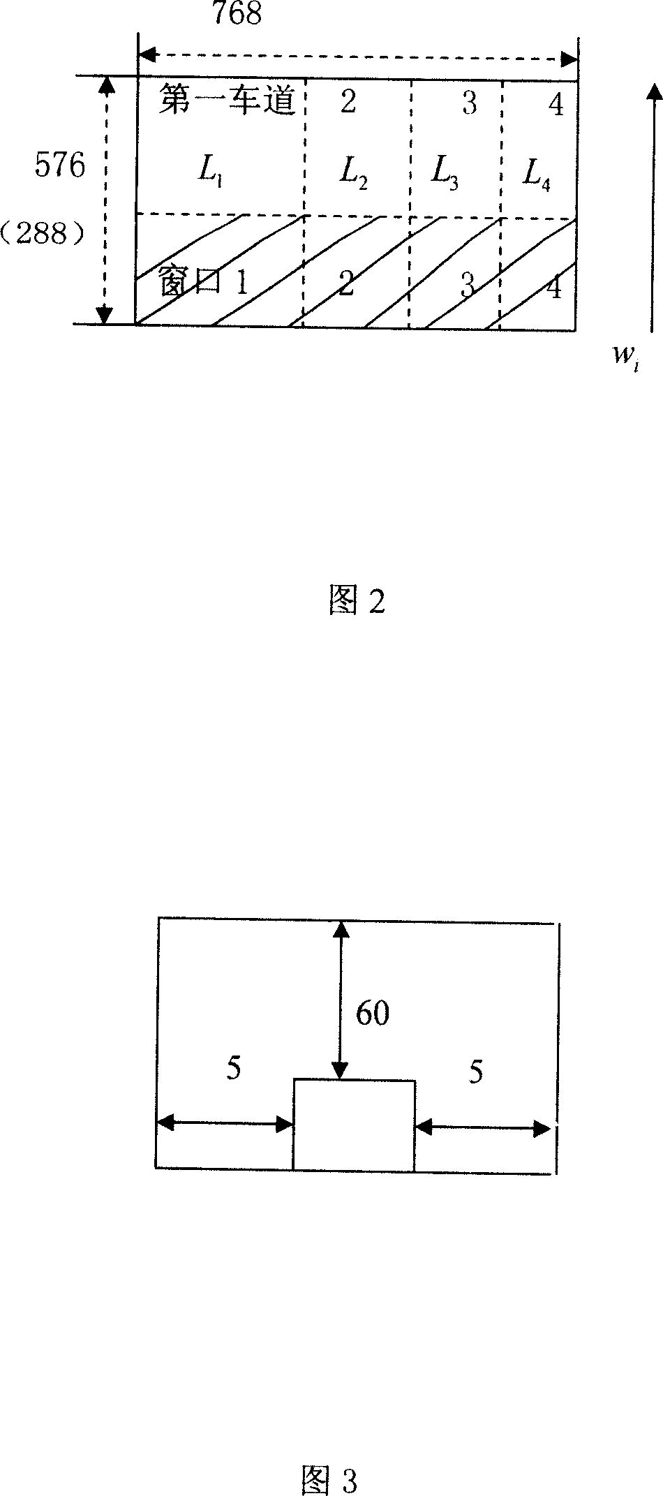
[0020] Referring to Fig. 3 below is that the inventive method is described further, and the concrete content of its main part is as follows:

[0021] 1. Average instantaneous position velocity

[0022] 1.1 field of view

[0023] Figure 1 illustrates.

[0024] Frame image 768×576

[0025] Field image 768×288

[0026] Thin line 384 or 256

[0027] Li = 384 4 = 96

[0028] Mi=64→128(to be determined)

[0029] 1.2 Motion detection

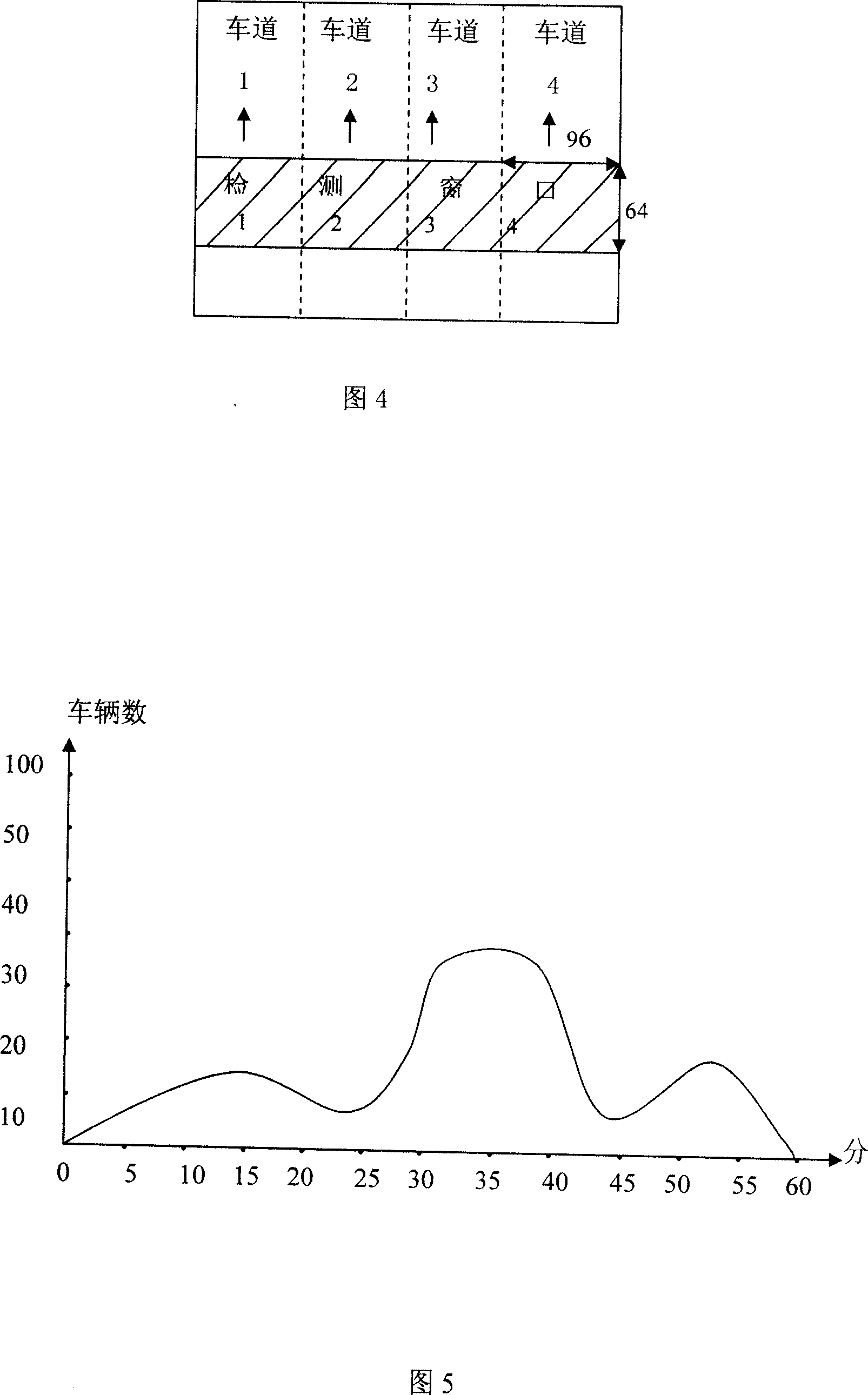
[0030] The camera is fixed on the pole in the air, overlooking the lanes, as shown in Figure 1, the number of lanes can be 2-4. The commonly used moving target detection method is the difference method. The difference method is to extract the target information by using the gray level difference of the image pixels of two adjacent frames or fields. For the stable part in the continuous image, its gray value is approximately 0, while the moving part shows a ...


PUM


Abstract

This invention relates to visual frequency speed testing method, which comprises the following steps: testing movement, track description; even speed computer, super speed judging and car flow statistics and is based on movement test technique according to image process technique, image trace technique and computer technique. This invention uses hardware platform as cameral machine and computer hardware to realize this invention widely used in road automotive speed testing and other situations.

Description

technical field [0001] The invention is developed according to motion detection technology, target image tracking technology and computer technology in the field of image processing technology, and the speed measurement accuracy can reach ±1km / h. Background technique [0002] With the rapid development of the country's economy, the construction of expressways in our country is changing with each passing day. The density of vehicles driving on the highway is getting bigger and bigger, and the speed is getting faster and faster. The cases of speeding traffic accidents are on the rise. This has become an urgent problem for the traffic department to solve. [0003] At present, the speed measurement systems that can be completed include: radar speed measurement, laser speed measurement and video speed measurement. The principles are as follows: [0004] (1) Laser speed measurement [0005] Laser speed measurement uses the ratio of multiple distance measurements to time to measu...

Claims


Application Information

Patent Timeline
IPC IPC(8): G08G1/01G08G1/052G08G1/054G08G1/065H04N5/14G01P3/36
Inventor 王海燕
Owner 王海燕
Learn More