

A plasma display plate with cross structure of opening at the grid hole of aperture mask
A technology of plasma and mesh holes, which is applied in the direction of tube structure parts, solid cathode parts, gas discharge tubes/containers, etc., and can solve the problems of low luminous brightness and efficiency
- Summary
- Abstract
- Description
- Claims
- Application Information
AI Technical Summary
Problems solved by technology
Method used
Image

Examples
Embodiment 1
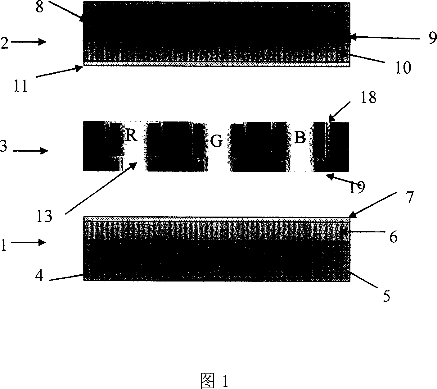
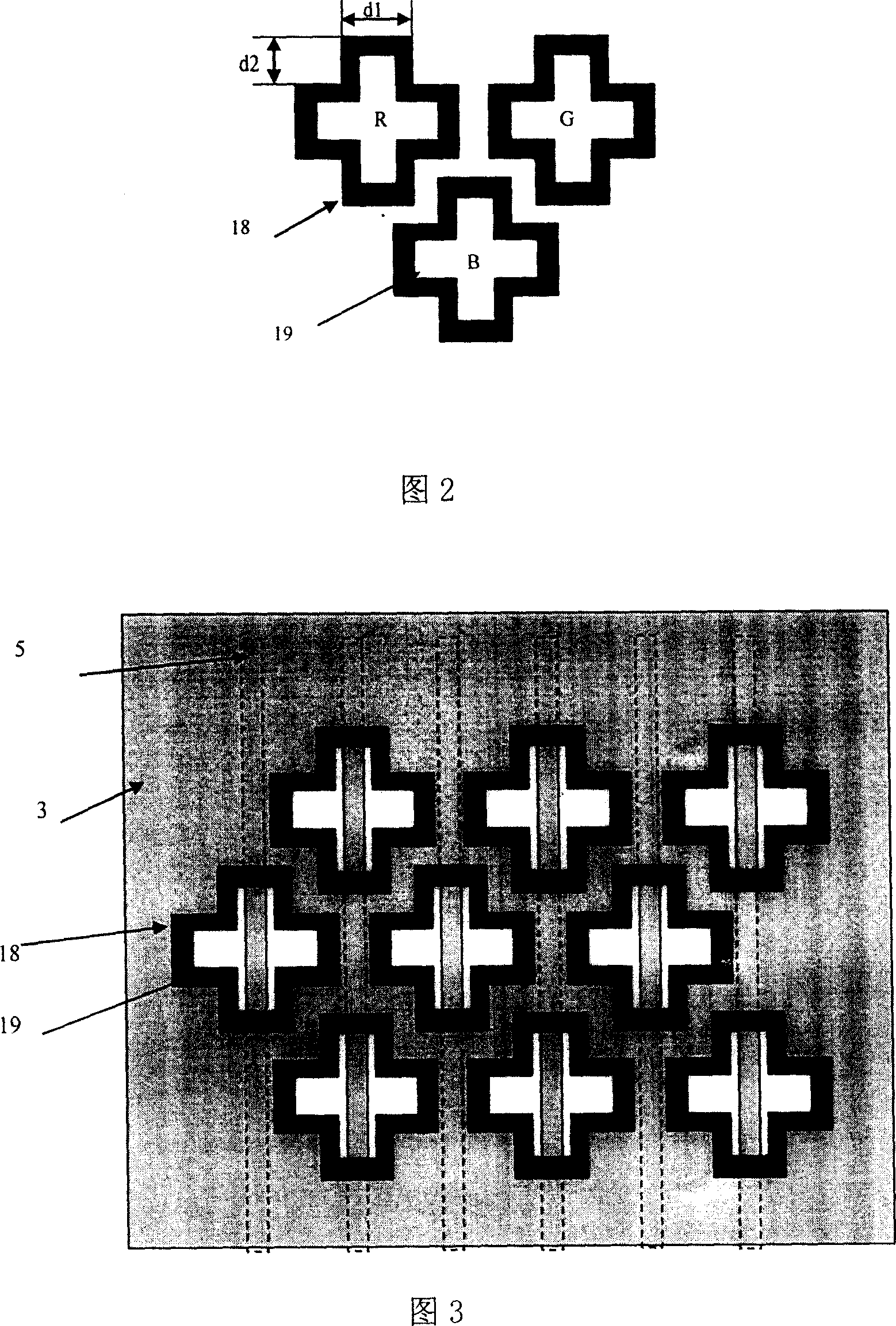
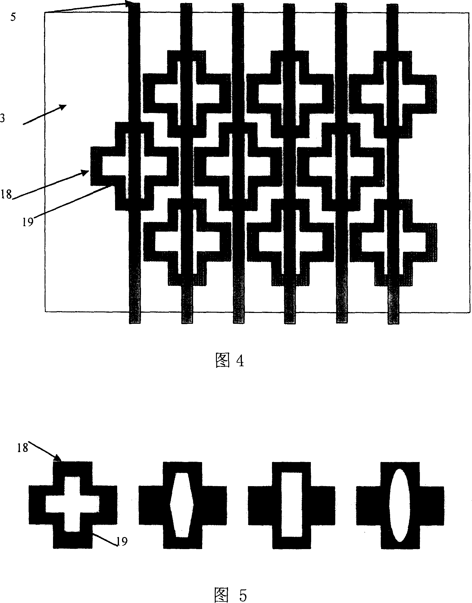
[0022] A plasma display panel with cross-shaped openings on grid holes of a shadow mask mainly consists of a rear substrate 1 , a shadow mask 3 and a front substrate 2 . The rear substrate 1 comprises a rear substrate glass substrate 4, the first electrode group 5 formed on the rear substrate glass substrate 4 is usually called a column electrode group or an address electrode group, and the rear substrate covering the first electrode group 5 The dielectric layer 6 formed on the glass substrate 4, the protective film 7 formed on the dielectric layer 6 surface; An electrode group 5 forms a second electrode group 9 vertically perpendicular to the space, commonly referred to as a row electrode group or a scanning electrode group, and a dielectric layer 10 formed on the surface of the front substrate glass substrate 8 covering the second electrode group 9, The protective film 11 formed on the dielectric layer 10; the shadow mask 3 sandwiched between the front and rear substrates 1,...
Embodiment 2
[0024] A plasma display panel with cross-shaped openings on grid holes of a shadow mask mainly consists of a rear substrate 1 , a shadow mask 3 and a front substrate 2 . The rear substrate 1 comprises a rear substrate glass substrate 4, the first electrode group 5 formed on the rear substrate glass substrate 4 is usually called a column electrode group or an address electrode group, and the rear substrate covering the first electrode group 5 The dielectric layer 6 formed on the glass substrate 4, the protective film 7 formed on the dielectric layer 6 surface; An electrode group 5 forms a second electrode group 9 vertically perpendicular to the space, commonly referred to as a row electrode group or a scanning electrode group, and a dielectric layer 10 formed on the surface of the front substrate glass substrate 8 covering the second electrode group 9, The protective film 11 formed on the dielectric layer 10; the shadow mask 3 sandwiched between the front and rear substrates 1,...
Embodiment 3
[0026]A plasma display panel with cross-shaped openings on grid holes of a shadow mask mainly consists of a rear substrate 1 , a shadow mask 3 and a front substrate 2 . The rear substrate 1 comprises a rear substrate glass substrate 4, the first electrode group 5 formed on the rear substrate glass substrate 4 is usually called a column electrode group or an address electrode group, and the rear substrate covering the first electrode group 5 The dielectric layer 6 formed on the glass substrate 4, the protective film 7 formed on the dielectric layer 6 surface; An electrode group 5 forms a second electrode group 9 vertically perpendicular to the space, commonly referred to as a row electrode group or a scanning electrode group, and a dielectric layer 10 formed on the surface of the front substrate glass substrate 8 covering the second electrode group 9, The protective film 11 formed on the dielectric layer 10; the shadow mask 3 sandwiched between the front and rear substrates 1, ...
PUM
| Property | Measurement | Unit |
|---|---|---|
| Thickness | aaaaa | aaaaa |
Abstract
Description
Claims
Application Information