Heat radiation method for transformer chamber

A technology of transformer room and heat dissipation method, which is applied in the field of power stations to achieve the effects of low ambient temperature, improving the environment and beautifying the environment

Inactive Publication Date: 2007-05-16
上海科宏变电设备有限公司
View PDF0 Cites 8 Cited by
  • Summary
  • Abstract
  • Description
  • Claims
  • Application Information

AI Technical Summary

Problems solved by technology

[0004] The purpose of the present invention is to overcome the shortcomings of the heat dissipation method used in the existing transformer room,

Method used


Image

  • Heat radiation method for transformer chamber
  • Heat radiation method for transformer chamber
  • Heat radiation method for transformer chamber

Examples


Example Embodiment

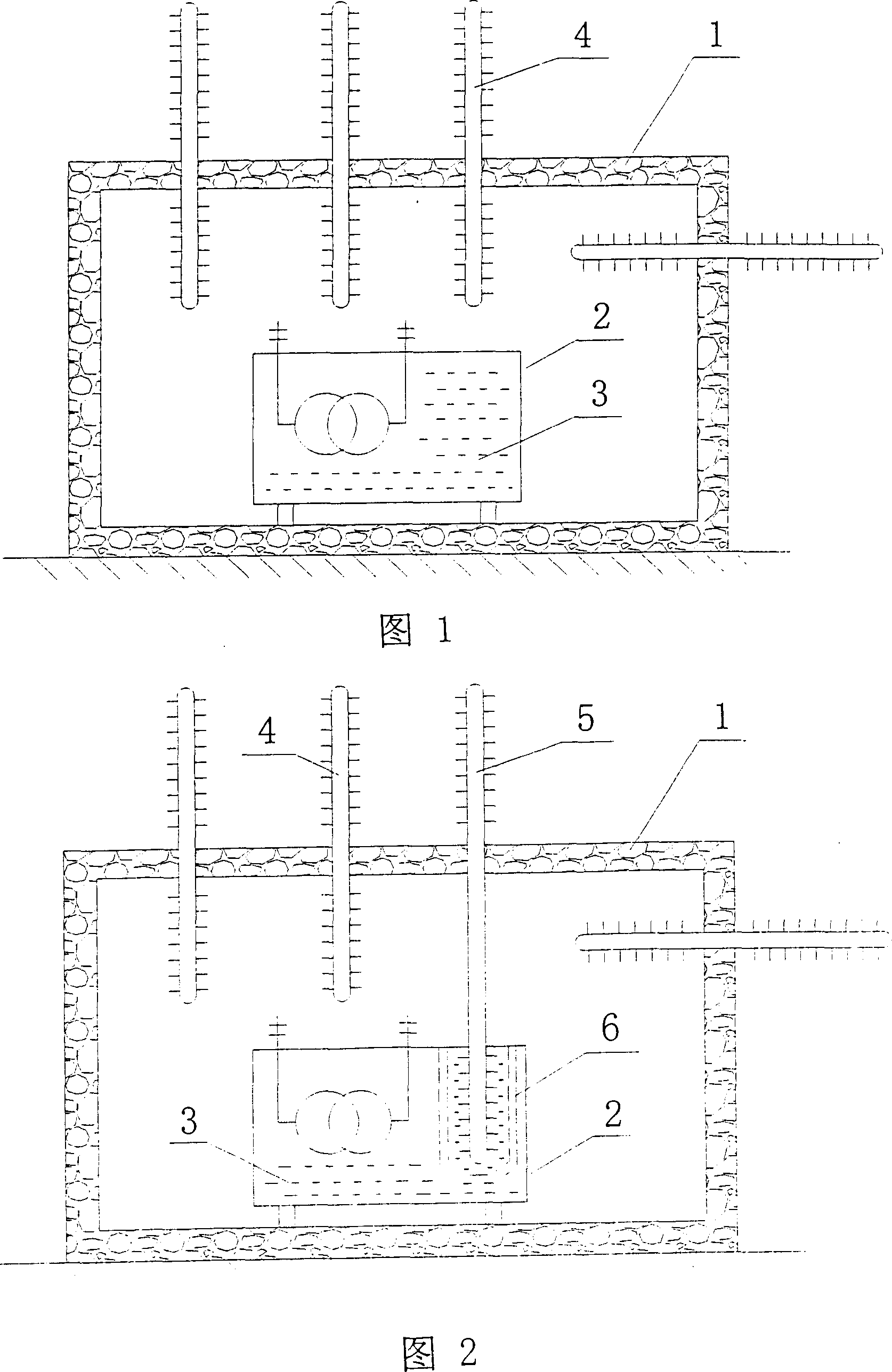
[0019] As shown in Figure 1, a heat dissipation method for a transformer room is characterized in that at least one set of heat pipes 4 composed of a heat absorption section, a heat dissipation section and a heat insulation section are inserted from the outdoors to the transformer room equipped with a transformer 2 or reactor In 1, the heat absorption section is placed indoors, the heat dissipation section is placed outdoors, and the adiabatic section is placed on the wall-through section. The heat absorption section absorbs the heat in the indoor air and transmits it to the heat dissipation section to be naturally emitted to the outdoor air. Each group of heat pipes can be composed of at least one heat pipe.

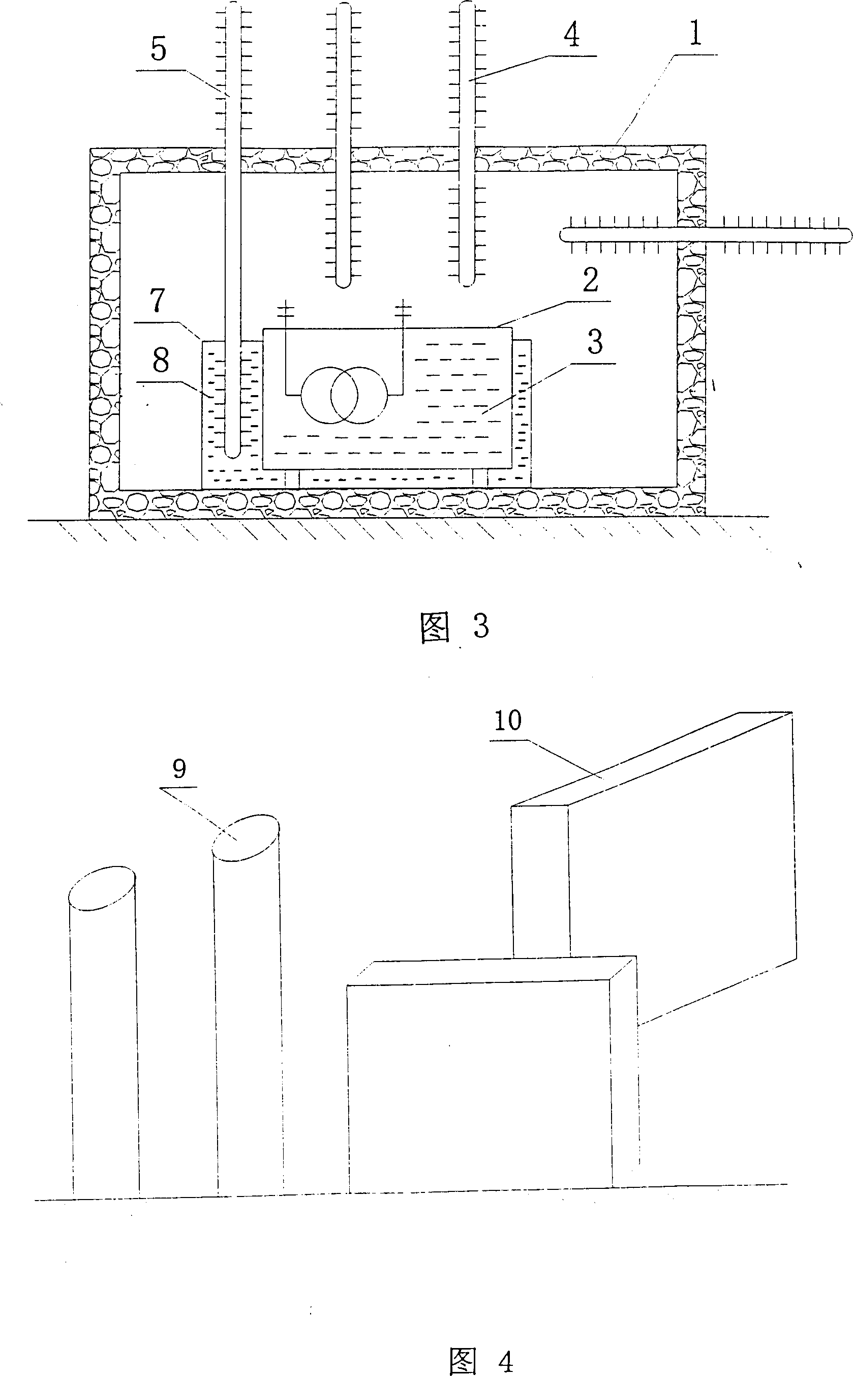
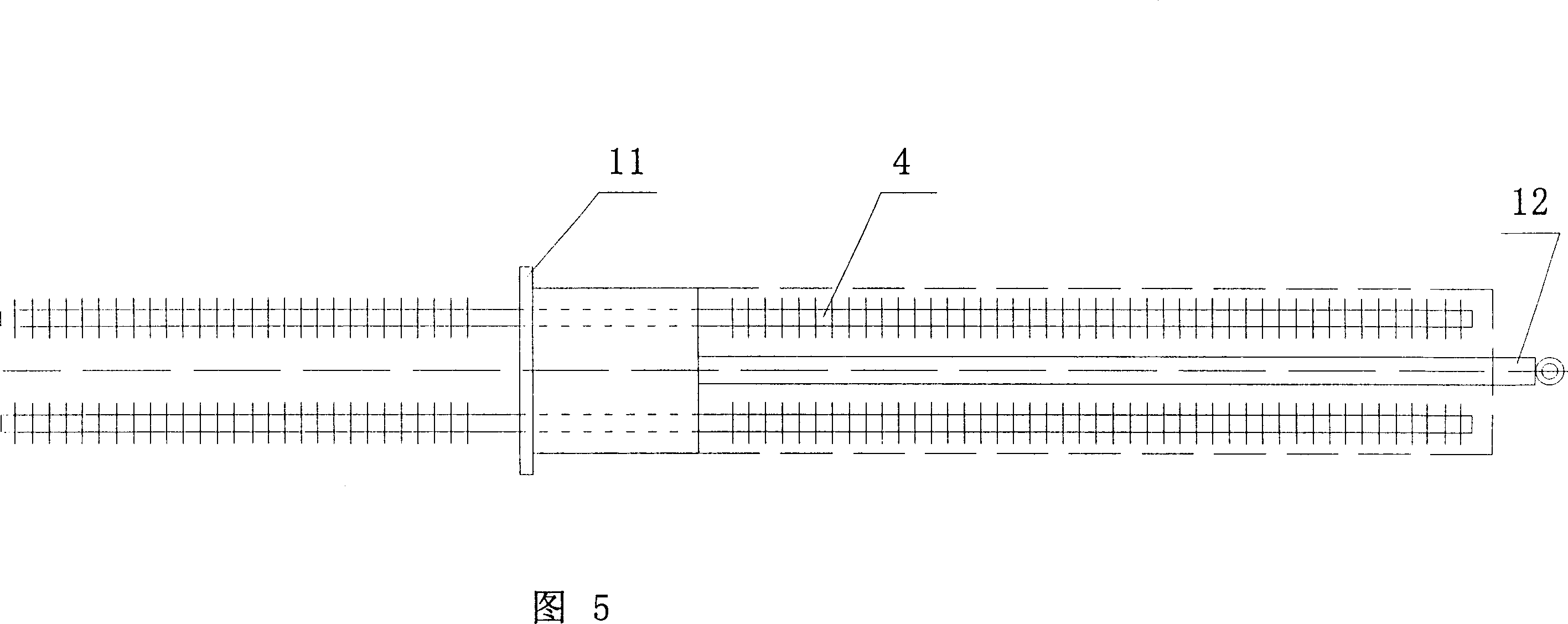
[0020] As shown in Figures 2 and 3, the heat absorption section of a group of heat pipes 5 is inserted into the oil 3 in the transformer tank or into the liquid 8 in the heat collecting tank 7 of the soaking transformer, and the heat is absorbed through the heat pipe and tr...


PUM


Abstract

The disclosed heat dispersion method for transformer vault comprises: inserting a heat pipe contained at least one group of heat absorption segment and dispersion segment and insulation segment into the transformer vault, while keeping heat absorption segment inside, the dispersion segment outside, and the insulation segment in the wall; absorbing gas heat in vault and heat in transformer oil and heat in heat-collection groove to release outside. This invention can save cost and improve environment.

Description

Technical field [0001] The invention relates to a heat dissipation method for a transformer room, and belongs to the technical field of power stations. Background technique [0002] In urban power supply, due to safety requirements, many transformers or reactors are installed indoors (in buildings). In recent years, due to the needs of urban landscaping, reduction of environmental noise and isolation of electromagnetic radiation, transformers and reactors are arranged in basements, especially in underground closed rooms, and become part of underground substations. Due to the large amount of heat generated during the operation of transformers, IEC 354-1991 and GB / T 15164-1994 "Guidelines for Loads of Oil-immersed Power Transformers" indicate that the heat generated by the transformer will increase the indoor ambient temperature and cause transformer oil and windings. The increase in temperature will affect the service life of the transformer. Therefore, the heat generated by the t...

Claims


Application Information

Patent Timeline
IPC IPC(8): H05K7/20G12B15/00F24F13/30
Inventor 孙兵曾庆赣
Owner 上海科宏变电设备有限公司
Why Eureka
Try Eureka