Method of increasing image bi-stability and grayscale accuracy in an electrophoretic display

A technology of electrophoretic display and display devices, which is applied in the direction of static indicators, instruments, etc., can solve the problem of complex acquisition of braking voltage data, and achieve the effects of improving gray scale accuracy, easy reproduction, and increased stability

Inactive Publication Date: 2007-05-16
KONINKLIJKE PHILIPS ELECTRONICS NV
View PDF2 Cites 8 Cited by
  • Summary
  • Abstract
  • Description
  • Claims
  • Application Information

AI Technical Summary

Problems solved by technology

[0011] However, the problem with US 2002 / 0005832 A1 is that in order to provide an accurate braking voltage, many factors must be considered, such as resistance of the dielectric fluid, image history, gray scale to be achieved, temperature, etc.
This makes the acquisition of brake voltage data quite complicated
Another problem is that it is not very energy efficient to apply energy to the particles in order to arrest said movement since a large amount of energy is required to increase the movement of the particles in order to produce the desired gray scale

Method used


Image

  • Method of increasing image bi-stability and grayscale accuracy in an electrophoretic display
  • Method of increasing image bi-stability and grayscale accuracy in an electrophoretic display
  • Method of increasing image bi-stability and grayscale accuracy in an electrophoretic display

Examples


Embodiment Construction

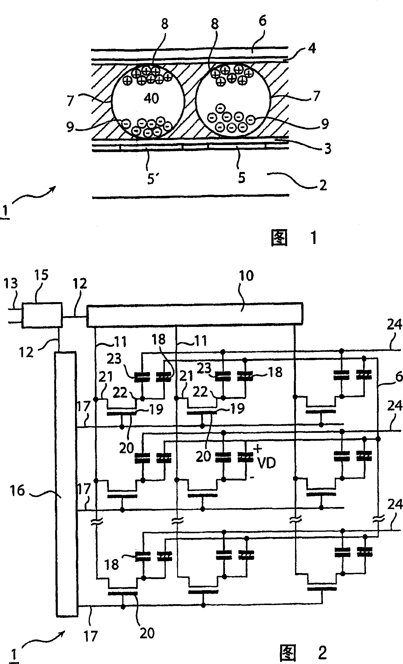
[0044] Fig. 1 shows a cross section of a part of an electrophoretic display device 1, which only shows a few picture elements for simplicity. The display device includes a base substrate 2 provided with an electrophoretic film of electronic ink, which exists between two transparent substrates 3 and 4. One of the substrates 3 is provided with transparent pixel electrodes 5 and 5 ′, and the other substrate 4 has a transparent counter electrode 6. The counter electrode can also be segmented. The electronic ink includes a plurality of microcapsules 7 of about 10 to 50 microns. Each microcapsule 7 includes negatively charged white particles 8 and positively charged black particles 9 suspended in a fluid 40.

[0045] The driving device 10 (see FIG. 2) is provided to provide a driving signal Vdr to the pixel electrodes 5, 5'to apply an electric field to some or all of the pixels 18 (FIG. 2), that is, to generate a potential difference across the pixels. When the pixel voltage VD across t...


PUM


Abstract

The present invention relates to an electrophoretic display device (1) and a method of controlling gray level transitions in an electrophoretic display device. The idea of the invention is that, in an electrophoretic device where drive signals (Dr) are applied to display device electrodes (5, 5') to effect movement of the display particles (8, 9), such that the particles correspond to image information to be displayed, a second electric signal (Ne) is applied to the display device electrodes. This second signal is arranged to decrease the ability of the particles to respond to the drive signal. By employing the second signal in accordance with the invention, more distinct optical states can be attained and the accuracy of the states becomes higher. Thus, the optical states are easier to reproduce due to a more well-defined particle control by means of the drive waveform according to the present invention.

Description

Technical field [0001] The invention relates to an electrophoretic display device and a method for controlling the gray level transition in the electrophoretic display device. Background technique [0002] Electrophoretic displays are well known in the prior art. The basic principle of the electrophoretic display is that the appearance of the electrophoretic medium encapsulated in the display can be controlled by an electric field. To this end, the electrophoretic medium typically includes charged particles having a first optical appearance (for example, black), and these charged particles are included in a fluid having a second optical appearance (for example, white) that is different from the first optical appearance, such as a liquid or air. The display typically includes a plurality of pixels, and each pixel can be individually controlled by an independent electric field provided by an electrode device. Therefore, the particles can move between the visible position and the in...

Claims


Application Information

Patent Timeline
Patent Type & Authority Applications(China)
IPC IPC(8): G09G3/34G09G3/20
CPCG09G2310/061G09G3/2014G09G2320/02G09G2310/06G09G2300/08G09G3/344
Inventor G·周E·M·J·奈森M·T·约翰逊
Owner KONINKLIJKE PHILIPS ELECTRONICS NV
Why Eureka
Try Eureka