Ultrasonic transducer and ultrasonic speaker using the same

一种超声换能器、固定电极的技术,应用在换能器电路、压电/电致伸缩换能器谐振换能器、压电/电致伸缩换能器等方向,能够解决不能保持振动膜振动的对称性质、频带窄、声音质量低等问题

Inactive Publication Date: 2007-05-16
SEIKO EPSON CORP
View PDF2 Cites 12 Cited by
  • Summary
  • Abstract
  • Description
  • Claims
  • Application Information

AI Technical Summary

Problems solved by technology

That is, in an ultrasonic speaker, the original audio signal cannot be demodulated with fidelity unless a high sound pressure in the 20 kHz band is secured in the ultrasonic region
[0020] It is easy to understand that it is difficult to reproduce (demodulate) a wide frequency band of 20 kHz with fidelity by a resonant ultrasonic speaker using a conventional piezoelectric element
[0021] Actually, the ultrasonic speaker using the conventional resonant ultrasonic transducer shown in Fig. 6 has the following problems: (1) the frequency band is narrow and the reproduced sound quality is low; (2) if the AM modulation coefficient is too high, the demodulated The sound will be distorted, so the modulation factor can be increased up to about 0.5; (3) If the input voltage is increased (if the volume is increased), the vibration of the piezoelectric element becomes unstable and the sound is distorted
But there is a problem: the absolute sound pressure is not enough to make the demodulated sound have enough volume
[0023] In addition, in the pull-type ultrasonic transducer, the electrostatic force acts only in the direction attracted by the fixed electrode side, so the symmetrical nature of the vibration of the vibrating membrane (corresponding to the upper electrode 132 in FIG. 7 ) cannot be maintained.
Therefore, there is a problem that when a pull-type ultrasonic transducer is used as an ultrasonic speaker, the vibration of the diaphragm directly produces audible sound

Method used


Image

  • Ultrasonic transducer and ultrasonic speaker using the same
  • Ultrasonic transducer and ultrasonic speaker using the same
  • Ultrasonic transducer and ultrasonic speaker using the same

Examples


Embodiment Construction

[0082] Embodiments of the present invention will be described in detail with reference to the accompanying drawings.

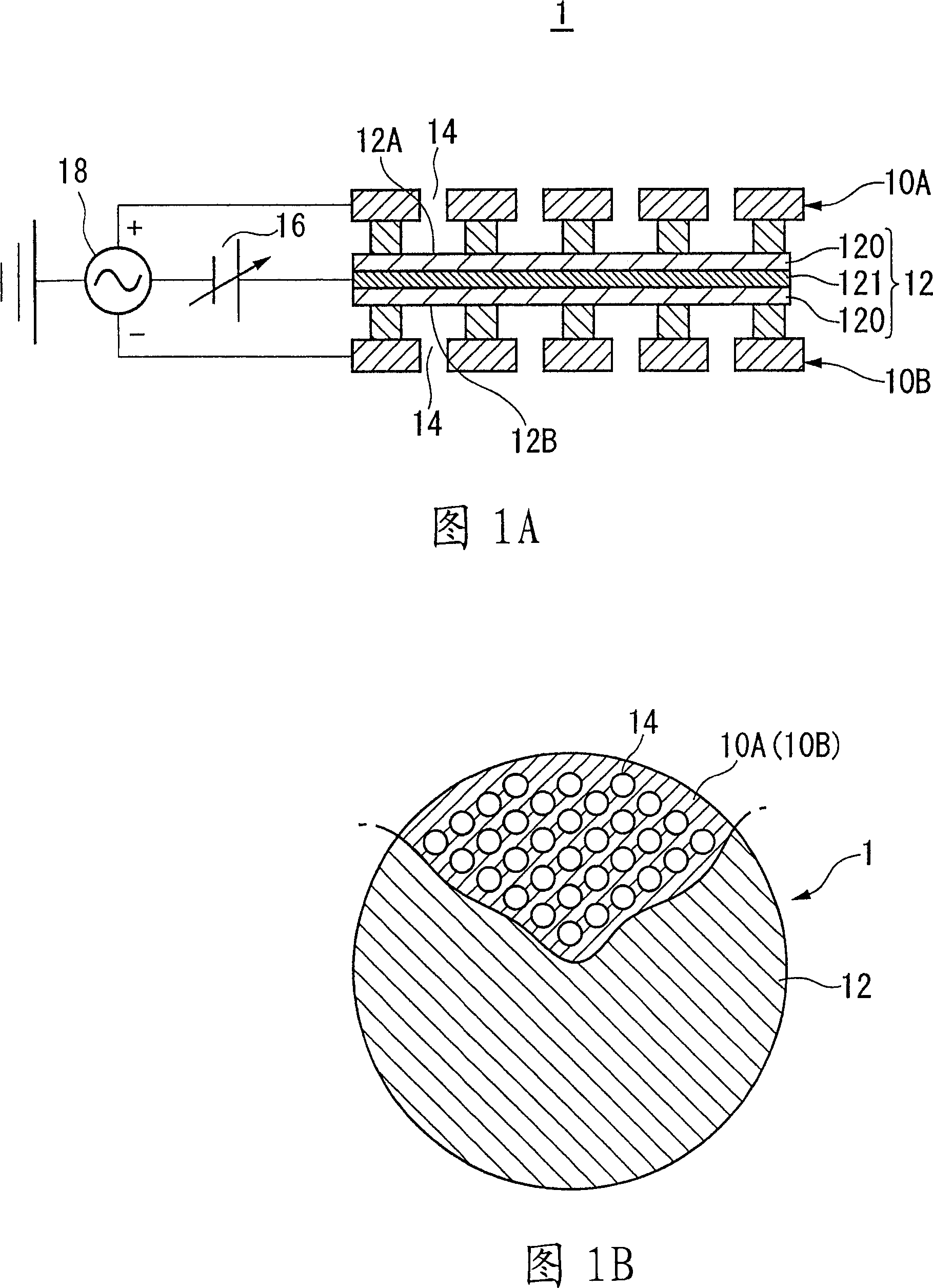
[0083] In FIGS. 1A and 1B , an ultrasonic transducer 1 according to the present embodiment includes: a pair of fixed electrodes 10A and 10B including a conductive member formed of a conductive material serving as electrodes; a vibrating membrane 12 having a conductive layer 121 and sandwiched between the pair of fixed electrodes; and a member holding the pair of fixed electrodes 10A and 10B and the vibrating membrane 12 (not shown in FIG. 1A or 1B, but having substantially the same the same structure as the housing 130). Hereinafter, the pair of fixed electrodes 10A and 10B may be referred to as a first fixed electrode 10A and a second fixed electrode 10B, respectively.

[0084] The vibrating membrane 12 is formed with a non-conductive body 120 and has an electrode layer 121 formed of a conductive material. A DC bias voltage having a single polarity (which m...


PUM


Abstract

The invention relates to an ultrasonic transducer and ultrasonic speaker using the same. The ultrasonic transducer includes: a pair of fixed electrodes including a conductive member; a vibrating film having a conductive layer; and a member which holds the pair of fixed electrodes and the vibrating film. The vibrating film is formed of nonconductive bodies and has an electrode layer formed of a conductive material. The electrode layer is applied with a DC bias voltage of a single polarity by a DC bias supply, and is also applied with an AC signal output from a signal source superimposed on the DC bias voltage. The pair of fixed electrodes have a plurality of holes of the same number at positions facing each other via the vibrating film, and an AC signal is applied between the conductive members of the pair of fixed electrodes by the signal source.

Description

technical field [0001] The present invention relates to an electrostatic ultrasonic transducer generating a constant high sound pressure over a wide frequency band and an ultrasonic speaker using the same. Background technique [0002] Fig. 6 shows the structure of a conventional ultrasonic transducer. Most conventional ultrasonic transducers are resonant ultrasonic transducers using piezoelectric ceramics as vibrating elements. The ultrasonic transducer shown in FIG. 6 uses piezoelectric ceramics as a vibrating element to perform conversion from electric signals to ultrasonic waves and vice versa (transmission and reception of ultrasonic waves). The bimorph type ultrasonic transducer shown in FIG. 6 includes two piezoelectric ceramics 61 and 62 , a cone 63 , a housing 64 , lead wires 65 and 66 and a shielding net 67 . [0003] The piezoelectric ceramics 61 and 62 are pasted together, and lead wires 65 and 66 are respectively connected to the ceramics 61 and 62 at surfaces...

Claims


Application Information

Patent Timeline
Patent Type & Authority Applications(China)
IPC IPC(8): H04R3/00H04R17/00H04R17/10
CPCH04R2217/03H04R17/005
Inventor 松泽欣也关野博一福井芳树宫崎新一
Owner SEIKO EPSON CORP
Why Eureka
Try Eureka